
Cooling cover, cooling cover components and cooling tubular armature

a cooling mat and component technology, applied in the field of cooling ceilings, can solve the problems of high cooling loss, condensation, unfavorable germ transmission, etc., and achieve the effect of flexible building progress, saving the calculated cooling mat area, and high degree of efficiency in operation

Inactive Publication Date: 2005-08-02
WEBER REINER +1
View PDF10 Cites 18 Cited by
  • Summary
  • Abstract
  • Description
  • Claims
  • Application Information

AI Technical Summary

Benefits of technology

[0011]The object of the present invention is to provide a cooling ceiling construction which has a high degree of efficiency in operation, which enables a very flexible building progress, offers many possibilities for lighting and installation, preferably achieves a fire protection of at least F 30 without the need to check the lower ceiling, can be installed in high rooms at the desired level, for example in old buildings, without additional lower ceilings, can be used as a carrier for sound insulating plasters or paints, and enables a saving of the calculated cooling mat area to be achieved.
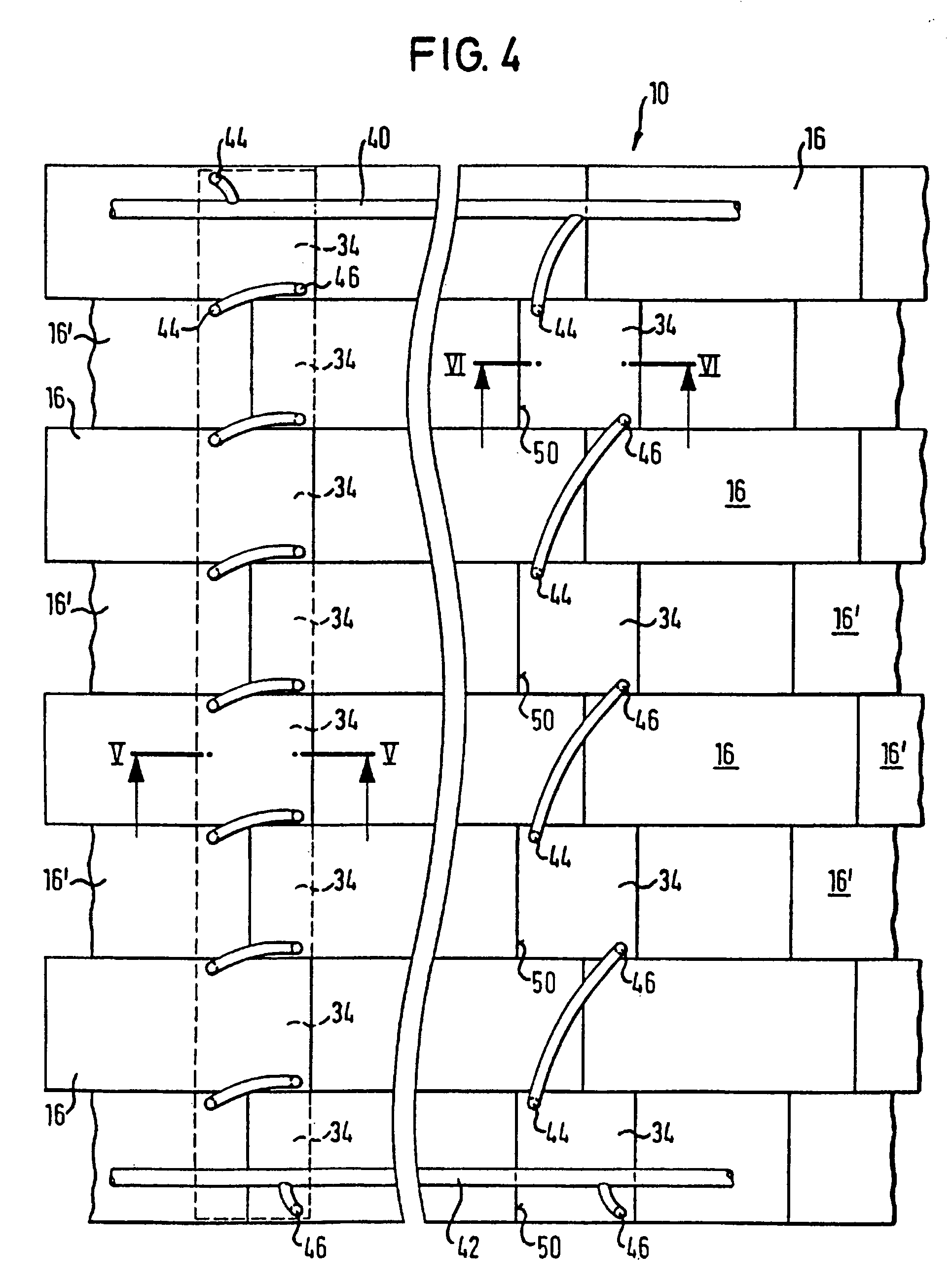
[0014]The cooling ceiling of the present invention is thus a construction which can be manufactured in dry building manner. It is assembled from building elements which are known per se and which are available at a favorable price in sizes which are easy to handle. Thus the building progress is not impaired by the installation of a cooling ceiling. This installation is in principle no more complicated than the installation of a normal built-in ceiling.
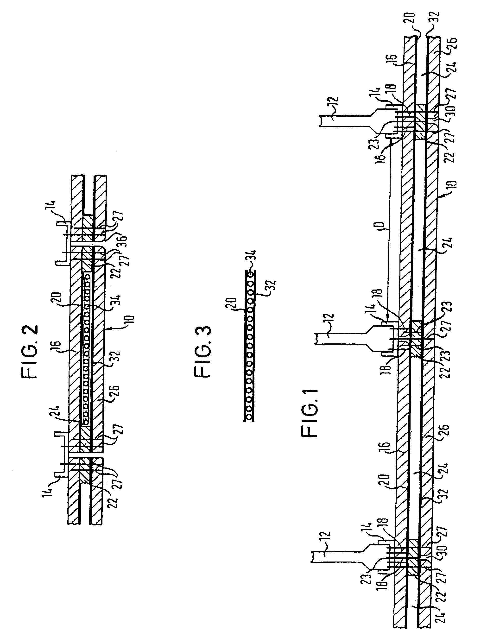
[0017]Embodiments of the present invention provide advantages. For example, after completion of the hanger construction and the attachment of CD sections to the individual hangers the upper panels can be attached to the CD sections by means of rapid construction screws. The aluminium foil, which is preferably provided, is preferably previously laminated onto the lower sides of the upper panels. This can, however, optionally take place after the mounting of the upper panels. Then the bars, for example in the form of plaster bars which are available at a favorable price and which are intended to serve as spacers, are secured to the upper panels by means of further rapid construction screws. Thereafter the cooling mats are inserted into the hollow cavities between the bars and are held in the so-formed hollow cavities by the attachment of the lower dry building panels, with the lower dry building panels likewise being secured by means of rapid construction screws at the positions of the spacers and with the rapid building screws being able to pass both through the plaster bars as well as through the upper dry building panels and optionally the CD sections of the carrier system. Thereafter it is only necessary, if desired, to fill in or tape over the gaps between the lower dry building panels. If desired an acoustically insulating fleece can be provided at the upper side of the lower dry building panels or can be attached in the form of a wallpaper to the lower side of the lower dry building panels.
[0018]A cooling ceiling of a second variant of the invention, in which the tubes of the cooling tube mats are embedded in a material, has the special advantage that the embedding material on the one hand represents an insulation towards the top, so that the cooling tube mats can be accommodated in cut-outs of the surface without upper dry building panels without having to fear a pronounced cooling loss upwardly. Moreover, with a construction of this kind, a ceiling is produced which has essentially only the thickness of one dry building panel, even when the cooling tube mats have an increased thickness in order to obtain better insulation, with the weight of the ceiling construction being relatively small. The lower side of the cooling ceiling then presents itself either as a continuous closed surface (after the closing of the transitions between the dry building panels and between the dry building panels and the cooling tube mats, which in the manner previously known for dry building panels can take place by means of tapes and optionally with a filler composition), and this ceiling can if required be painted or papered or provided with a coating, for example of a glass fabric and / or of spray plaster. The cooling tubes can, if desired, have a flattened surface of the bottom which ensures a better cooling action downwardly and moreover enables a flat design of the lower side of the cooling ceiling, or they can, for example, have a circular or polygonal cross-section which is only embedded up to a half height in the embedding material, with the downwardly projection regions of the cooling tubes taking care of a decorative structuring of the lower side of the cooling ceiling, i.e. being capable of being used as a design feature. This variant has, however, also the advantage that the exposed surface of the cooling tubes is even larger relative to the flattened version, whereby the cooling action is increased still further. This increase of the cooling action signifies in turn that one can operate with lower temperature differences—whereby the danger of condensation is reduced—and / or can operate with a lower flow speed of the coolant, whereby the flow noises are reduced.

Problems solved by technology

Such air conditioning systems are relatively complicated, require regular servicing and as a rule, cause noise and can lead to an undesired transmission of germs.
Despite the advantages of cooling ceilings, the above-named system also has disadvantages.
In the system in which the cooling mats and cooling pipes are used in connection with metal ceilings, there is a high cooling loss upwardly.
Through the laying of cooling mats in plaster, the danger also exists of condensation arising which has the consequence that the cover layer separates from the cooling mats, or tears, or that ugly spots arise.
Moreover, in both of the above-named systems hindering, of the building progress and other works is unavoidable.

Method used


Image

  • Cooling cover, cooling cover components and cooling tubular armature
  • Cooling cover, cooling cover components and cooling tubular armature
  • Cooling cover, cooling cover components and cooling tubular armature

Examples


Embodiment Construction

[0037]FIG. 1 shows a part cross-section through a cooling ceiling 10, which is executed in this example as a suspended ceiling. For this hangers 12 are provided which can be secured to a bare ceiling or to an old ceiling. Below these hangers there are located so-called CD sections 14 which serve as carrier rails and which are well known per se, as also are the hangers. In this example the spacing (center-to-center spacing) D from carrier rail to cater rail amounts to a maximum of 625 mm. Sandwich-type plaster board panels 16 with dimensions of 2000 mm length, 1250 mm width and 12.5 mm thickness are secured to the CD ceiling sections 14 from below with the aid of rapid construction screws 18. These have, for example, a length of 25 mm. The invention is not restricted to these preferred dimensions, as quoted. Boards with other dimensions can be used, for example, board thicknesses in the customary range from 9.5 mm to 18 mm can be straightforwardly selected.

[0038]An aluminium foil 20 ...


PUM


Abstract

The present invention concerns a cooling cover (10) comprising cooling tubular armatures (34) applied against said cooling cover or against an existing cover. The cooling cover is characterized by a sandwich-type assembly of dry-process manufactured upper and lower firestop plates (16, 26) of gypsum plasterboard or plaster mold, separated by spacers (22) so as to form plane cavities (24) where the cooling tubular armatures (16) are situated, the upper plates (16) preferably being provided with a firestop spacer or a heat reflecting layer, for instance an aluminum foil. In an other embodiment, the tubes of the cooling armature are embedded in a sealing material, resulting in a plate being placed either against the lower surface of the dry-process manufactured upper plates or against segments of this surface.

Description

BACKGROUND OF THE INVENTION[0001]1. Field of the Invention[0002]The present invention relates to a cooling ceiling consisting of cooling tube mats, in particular plastic cooling tube mats, which are attached or attachable to a bare ceiling, or to an existing ceiling, by means of a carrier system, and also relates to an element and to a cooling tube mat for use in such a cooling ceiling.[0003]2. Description of the Prior Art[0004]Cooling ceilings of the above-named kind are principally used, in known manner, in multiple stores, offices and larger buildings. The aim exists to cool the rooms, above all in summer and for this, two different system are known in principle which offer an alternative to air conditioning. In air conditioning, the room air is continually circulated and cooled to a preselectable temperature. Such air conditioning systems are relatively complicated, require regular servicing and as a rule, cause noise and can lead to an undesired transmission of germs.[0005]In a...

Claims


Application Information

Patent Timeline
IPC IPC(8): E04B9/02F24D3/16F24F5/00F24D3/12
CPCE04B9/02F24D3/165F24F5/0089F24F5/0092Y02B30/00
Inventor WEBER, REINERSCHWENDEMANN, MICHAEL
Owner WEBER REINER
Learn More