Coolant flow field design for fuel cell stacks

a fuel cell and flow field technology, applied in the field of pem fuel cells, can solve the problems of over-cooling some areas of the fuel cell while under-cooling other areas, and achieve the effects of reducing the amount of energy required, increasing the efficiency of the fuel cell stack, and reducing the required pumping power

Inactive Publication Date: 2005-08-02
GM GLOBAL TECH OPERATIONS LLC
View PDF15 Cites 28 Cited by
  • Summary
  • Abstract
  • Description
  • Claims
  • Application Information

AI Technical Summary

Benefits of technology

[0010]The present invention enables temperature uniformity to be achieved across the fuel cell stack, thereby enabling optimization of the reaction over the entire active area which, by definition, increases the efficiency of the fuel cell ...

Problems solved by technology

However, most bipolar plates (and monopolar end plates) have a coolant flow field configured to provide a consistent rate o...

Method used


Image

  • Coolant flow field design for fuel cell stacks
  • Coolant flow field design for fuel cell stacks
  • Coolant flow field design for fuel cell stacks

Examples


Embodiment Construction

[0022]The following description of the preferred embodiments is merely exemplary in nature and is in no way intended to limit the invention, its application, or uses.

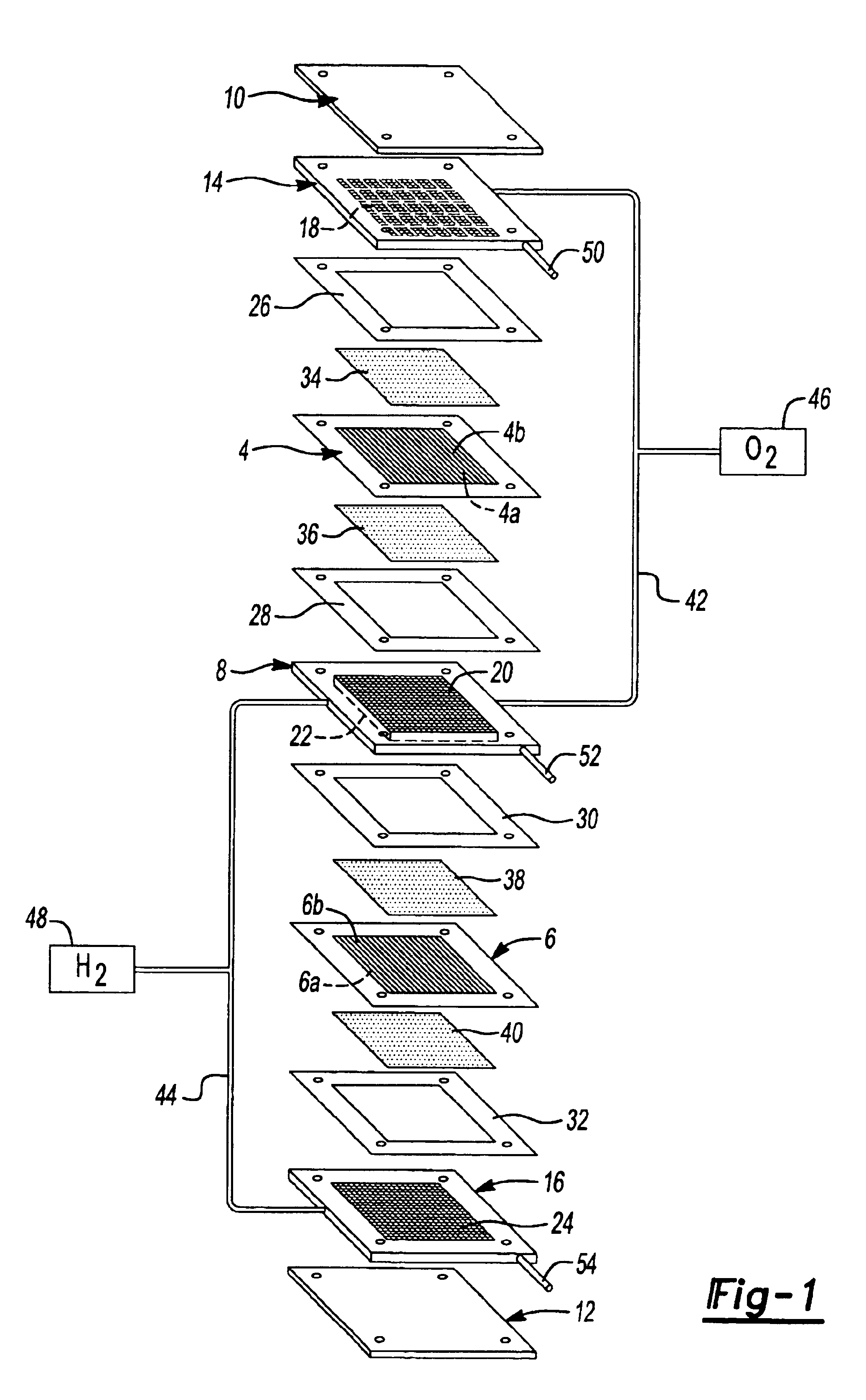
[0023]Before further describing the invention, it is useful to understand an exemplary fuel cell system within which the invention operates. Specifically, FIG. 1 schematically depicts a PEM fuel cell stack having a pair of membrane-electrode assemblies (MEAs) 4 and 6 separated from each other by a non-porous, electrically-conductive, liquid-cooled bipolar plate assembly 8. Each MEA 4 and 6 has a corresponding cathode face 4a, 6a and an anode face 4b and 6b. MEAs 4 and 6 and bipolar plate assembly 8 are stacked together between non-porous, electrically-conductive, liquid-cooled monopolar end plate assembly 14 and 16. Steel clamping plates 10 and 12 are provided for enclosing the exemplary fuel cell stack. Connectors (not shown) are attached to clamping plates 10 and 12 to provide positive and negative terminals for the f...


PUM


Abstract

A bipolar plate assembly is provided for use in a fuel cell stack to supply reactants to the anode and cathode sides of fuel cells within the stack. The bipolar plate assembly includes first and second sub-plates, each including a first face surface having a coolant flow field formed therein and a second face surface having a reactant flow field formed therein. The coolant fields of the first and second sub-plates include regions of varying flow volume, having respective flow resistance therebetween. The regions of varying flow volume enable variable cooling across the fuel cell stack, thereby enabling a constant temperature to be achieved across the fuel cell stack.

Description

FIELD OF THE INVENTION[0001]This invention relates generally to PEM fuel cells and more particularly to bipolar plates for separating adjacent fuel cells in a fuel cell stack.BACKGROUND OF THE INVENTION[0002]Fuel cells have been used as a power source in many applications. For example, fuel cells have been proposed for use in electrical vehicular power plants to replace internal combustion engines. In proton exchange membrane (PEM) type fuel cells, hydrogen is supplied to the anode of the fuel cell and oxygen is supplied as the oxidant to the cathode. PEM fuel cells include a membrane electrode assembly (MEA) comprising a thin, proton transmissive, non-electrically conductive, solid polymer electrolyte membrane having the anode catalyst on one face and the cathode catalyst on the opposite face. The MEA is sandwiched between a pair of non-porous, electrically conductive elements or plates which (1) pass electrons from the anode of one fuel cell to the cathode of the adjacent cell of ...

Claims


Application Information

Patent Timeline
IPC IPC(8): H01M8/02H01M8/04H01M8/10
CPCH01M8/04029H01M8/04074H01M8/0202Y02E60/50
Inventor LEE, JAMES H.
Owner GM GLOBAL TECH OPERATIONS LLC
Why Eureka
Try Eureka