Devices in the first category have programmable logic blocks, interconnections, and I / O blocks, and their configuration memories are volatile; i.e., their data is lost upon power shutdown.
Since the SRAM cells used in this device are volatile, the configuration data on the
chip disappears when the power is removed.
The use of such an off-
chip non-
volatile memory raises the cost of products, besides consuming precious board space.
Other types of non-volatile memories such as PROM,
EPROM, electrically erasable PROM (
EEPROM), or
flash memory are not used in the second category, since they require the integration of high-
voltage transistors and their speed is insufficient to meet the needs of programmable logic devices.
Conventional FPGAs, however, have some problems, one of which is a limitation in the number of logic gates per unit
chip area.
One problem is, however, that the above publication tells us little about how to switch the configuration data.
Another problem is, of course, that their configuration memory is volatile.
This means that an external non-
volatile memory is necessary, which makes the board design more difficult since it increases the component count, costs, and board space consumption.
Yet another difficulty about DPGA is that no specific method of configuration switching is disclosed.
As a general problem with programmable logic devices, it is known that some improper internal connections could happen on power-up in the case the configuration memory has not been loaded with data.
If two driver outputs in opposite logic states are wired together, the conflict could produce an undefined
voltage level, resulting in a large current flow within a device.
This method of disabling output drivers has a
side effect that a device cannot start operation immediately after power-up.
Also, in conventional programmable logic devices, loading of their configuration data often takes a long time to complete.
Conventional devices, however, provide little security measures to protect such assets from stealing, tampering, or other unauthorized access.
This
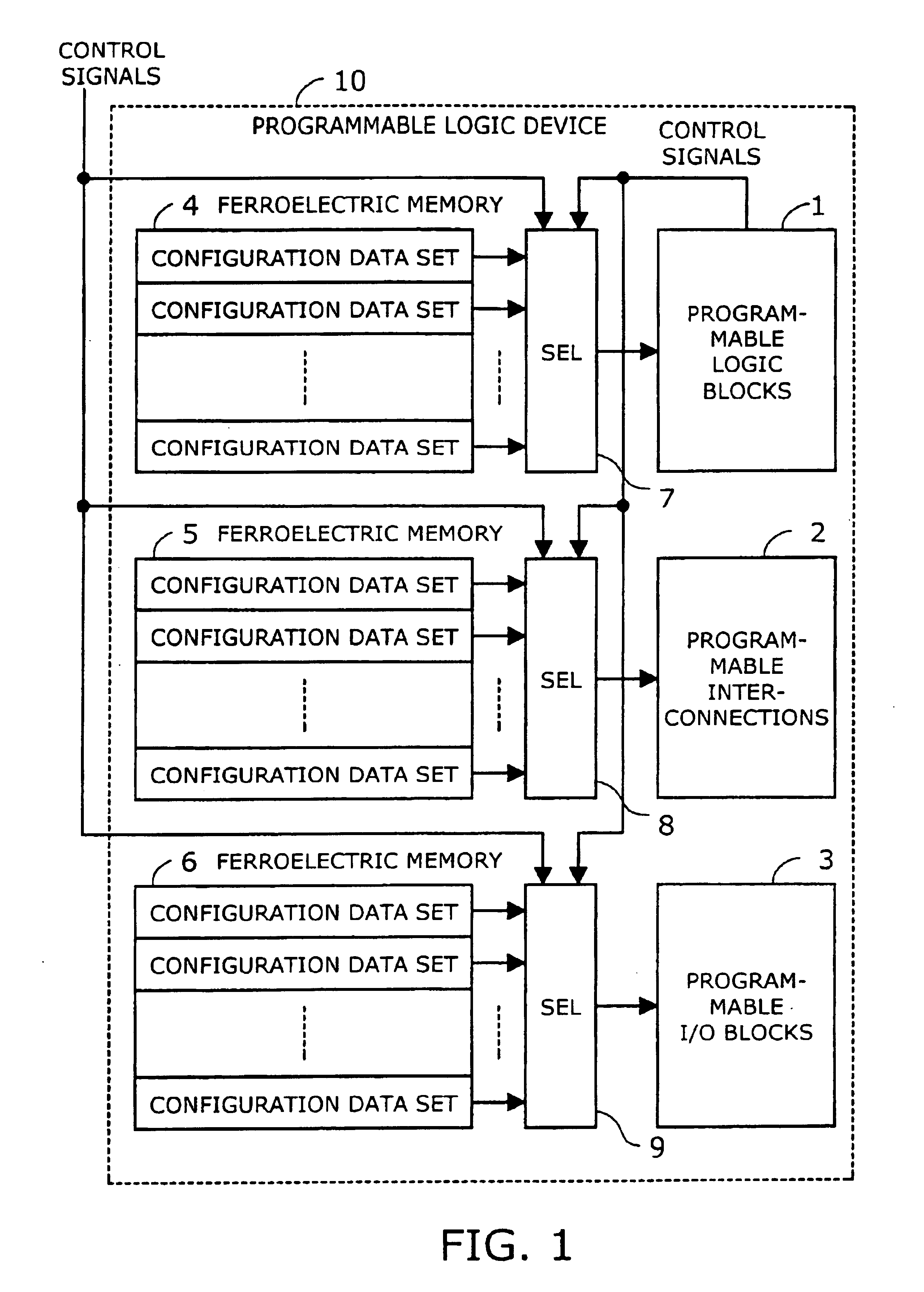
programmable logic device, however, may fail to recall data out of ferroelectric memories in power-up, or may fail to store data in ferroelectric memories in power-down. T. Tamura et al. wrote a report that reveals some dynamic behaviors of ferroelectric capacitors (T. Tamura et al., ISIF Digest, p.1.2.2, 2001).
That nature of capacitors could lead to a problem in recovering data from the polarization state of each
ferroelectric capacitor, as a consequence of application of a rapidly rising
voltage at the time of power-up.
It is known, however, that a
ferroelectric capacitor has a tendency to prefer one state over the other if a full supply voltage is applied to it for a long period of time.
This “imprint” effect, a phenomenon due to a shift of the
hysteresis loop, makes it difficult to write data to ferroelectric memory cells.

