
Measuring method for individual fibers of cables

a technology of individual fibers and cables, applied in the direction of measuring structures/machines, testing of fibre optic/optical waveguide devices, instruments, etc., can solve the problems of not being able to return to the starting point, requiring spatial separation, time- and cost-intensive, etc., and achieves low susceptibility to faults, high reflectivity, and greater accuracy and speed

Inactive Publication Date: 2005-08-02
DEUTSCHE TELEKOM AG
View PDF23 Cites 17 Cited by
  • Summary
  • Abstract
  • Description
  • Claims
  • Application Information

AI Technical Summary

Benefits of technology

[0010]A spatial separation of the transmitting and receiving stations of the measuring system is no longer required, because the measuring radiation is reflected at the end of the test fiber to the fiber input by a mirror, hereinafter referred to as a Schmidt mirror, having very high reflectivity (>99%), it being possible to measure the desired fiber parameter at the coupling-in, or injection, site. Furthermore, for the first time in practice, highly specialized personnel are able to evaluate the measuring results at only one end of the respective cable or fiber under test. In addition to the fact that there is no longer any need for the time- and cost-intensive spatial separation of transmitter and receiver, or the required personnel associated with it, it is also possible for the measurement results to be evaluated with considerably greater accuracy and speed. The arrangement has low susceptibility to faults owing to the fact that the highly reflective mirror coating can be applied to the end face of any fiber connector, so that the connector provided with the mirror coating is connected either directly or via a short glass-fiber or plastic-fiber cable piece terminated with a standard connector and with the mirror connector. The use of a glass-fiber cable piece thus prepared has the advantage that the mirror connector remains untouched and is treated with care. The reflected measuring radiation can be coupled out at the input end using a Y-coupler and supplied to the measuring method. Furthermore, instead of the Y-coupler, it is possible to employ in each of the two optical windows a circulator which has a considerably smaller insertion attenuation compared to the Y-coupler. In addition, the measuring method according to the present invention makes it possible to use just one circulator for both optical windows, i.e., in the entire spectral range of interest, this resulting in a slightly higher insertion attenuation. The measuring method according to the present invention includes the advantage that it can be used for measuring the chromatic dispersion, polarization mode dispersion and bandwidth of multimode glass and plastic fibers. Moreover, the method can be employed for high-precision attenuation measurements with cutback technique on installed glass-fiber or plastic-fiber cables, or in cases where, for laboratory measurements, both glass-fiber ends are in separate rooms.

Problems solved by technology

A fundamental problem with regard to field measurements on installed glass-fiber cables is the measuring of individual fibers.
Thus, it is not permissible to return to the starting point with the aid of a loop composed of two connected fibers, namely one fiber out and one fiber back.
On the other hand, the required spatial separation, for example up to 50 km in telephone networks, is time- and cost-intensive, or is not possible at all.
Particularly for PMD measurements, loop measurements are worthless, since the PMD values of the individual fibers of a cable may differ very greatly.
The problem of the required separation of transmitter and receiver is further complicated by the fact that various measuring methods either cannot be used at all in this case, such as the Jones Matrix Method for PMD measurements in the frequency domain, i.e. using the polarimeter, or that only unsatisfactory design approaches and / or devices necessary for this purpose, are known, as described in the J. Vobian, K. Mörl article cited above.
Generally, the synchronization of transmitter and receiver is problematic or costly in the case of separate measurements in the frequency domain.
This represents a major restriction in practice.
Since both the CD and the PMD measurements are by no means trivial, it is necessary—above all for evaluating the results obtained—to use highly qualified personnel at both ends of the link, which is very cost-intensive.
It is not suited for dispersion, bandwidth and PMD measurements, which are completely different than attenuation transmission measurements, since substantially more demanding and more complicated fiber parameters are involved.
Moreover, the reflector at the fiber end, in accordance with the above mentioned Patent Abstracts of Japan, is a completely normal reflector and not suited for measurements of complicated fiber parameters.
4%) of the fiber end face is used, as in the case of known OTDR measurements, however, this is far from being sufficient for the required measurements.

Method used


Image

  • Measuring method for individual fibers of cables
  • Measuring method for individual fibers of cables
  • Measuring method for individual fibers of cables

Examples


Embodiment Construction

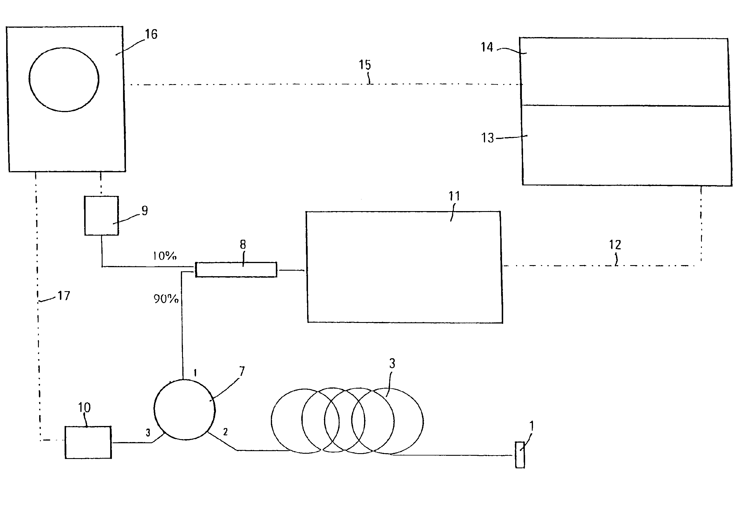
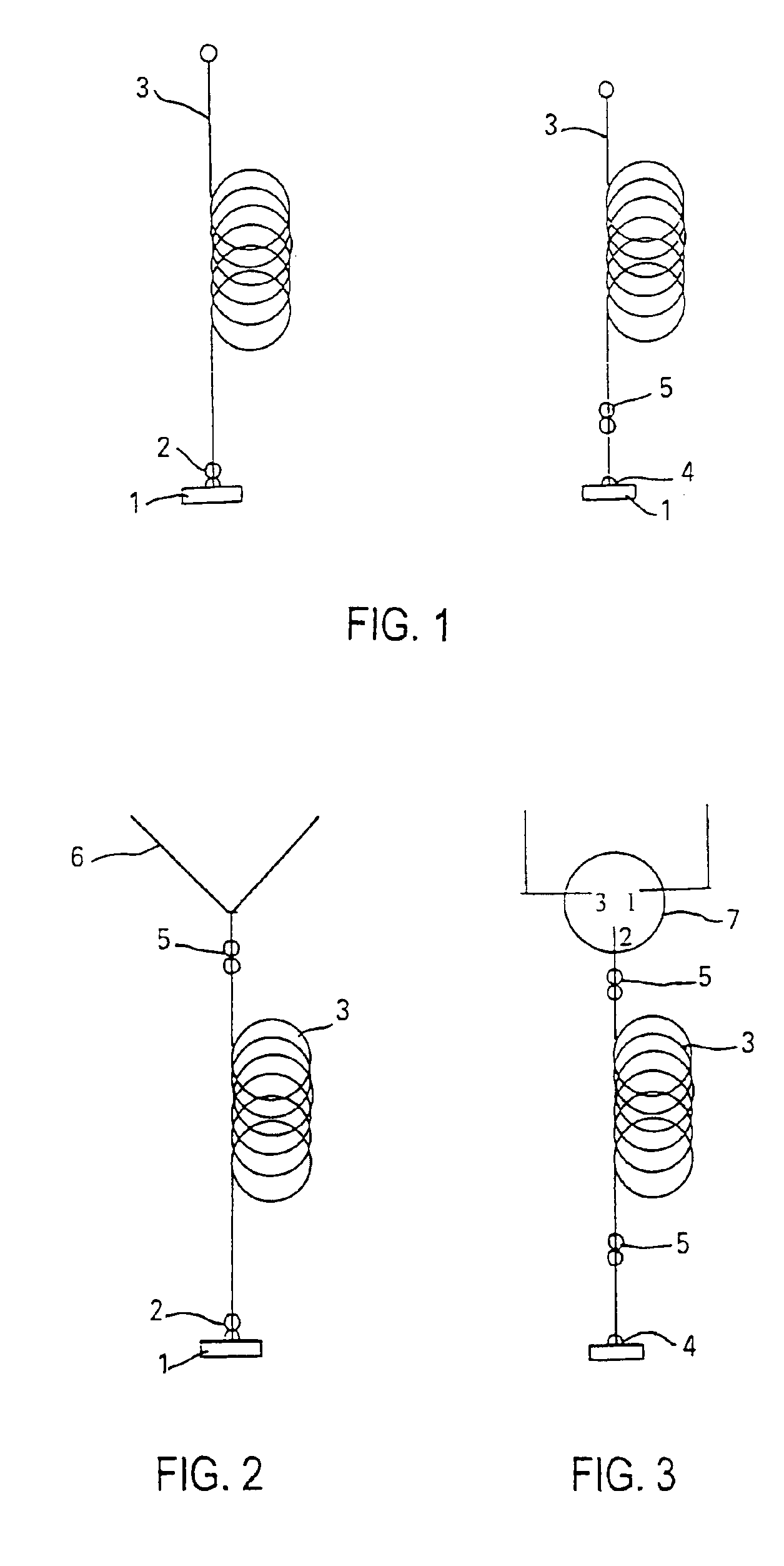
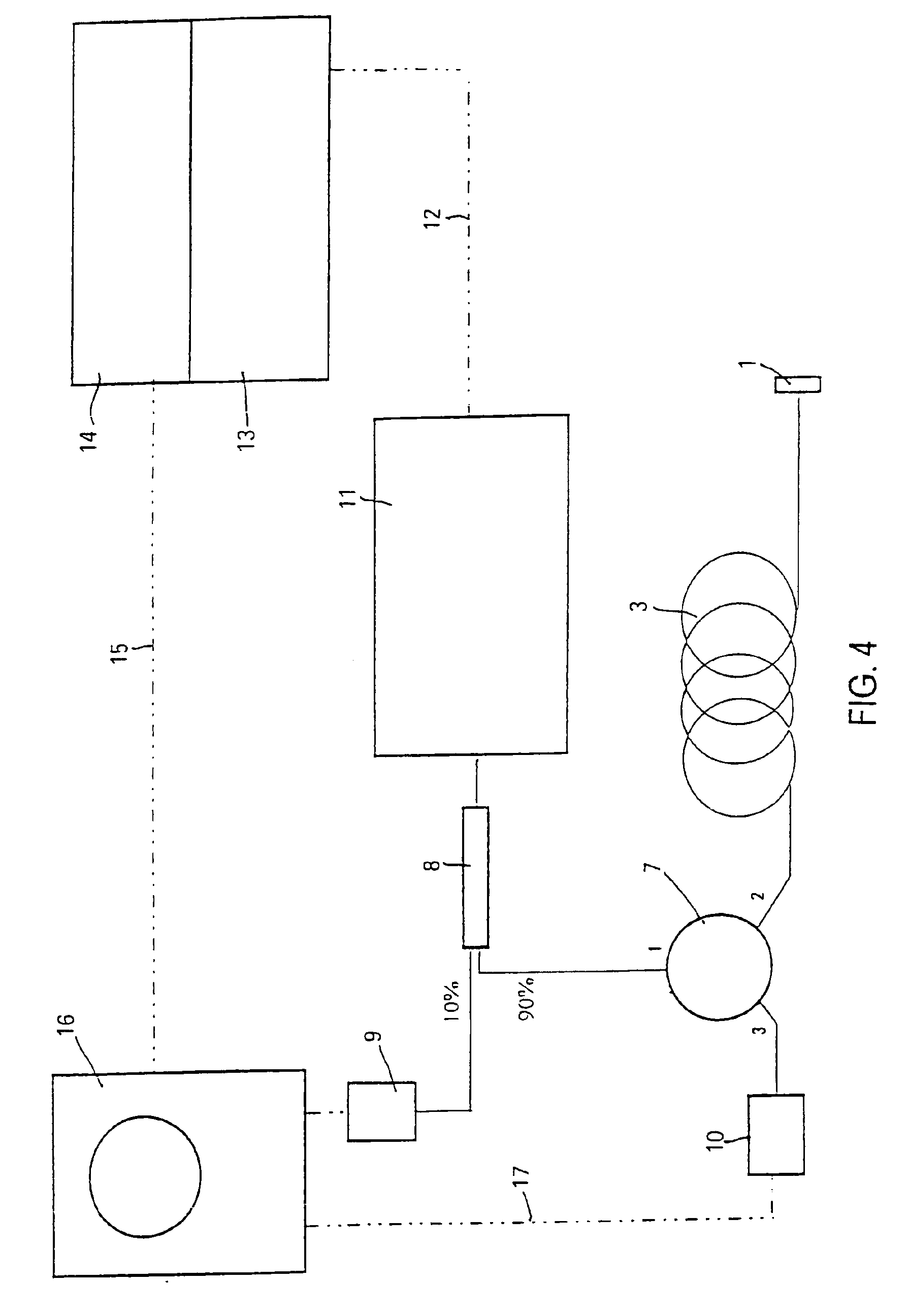
[0020]FIG. 1 demonstrates the measuring principle of a method for measuring relevant parameters of individual fibers of a cable according to the present invention. On the left side, a Schmidt mirror 1 on a fiber connector 2 is connected directly to a test fiber 3, and shown in the right-hand diagram is a glass-fiber cable piece, terminated with a Schmidt mirror connector 4 and a standard connector 5 which is connected to test fiber 3. It is known, for example, from H. Döring, J. Peupelmann, F. Wenzel: “Pr3+-doped fiber laser using direct coated dichroic mirrors”, Electr. Lett. Vol. 31 (1995), No. 13, p. 1068, which is hereby incorporated by reference herein, that it is possible to apply mirrors and filters of various kinds as dielectric coating systems to the end faces of fiber connectors. In the present example, a highly reflective mirror having a reflectivity>99.8% in the spectral range between 1200 and 1650 nm under consideration is applied to the end face of a fiber connector, a...


PUM


Abstract

In a method for measuring relevant parameters of individual fibers of single-mode and multimode fibers of glass- or plastic-fiber cables, measuring radiation is reflected at the end of the test fiber to the fiber input by a mirror, particularly a Schmidt mirror having very high reflectivity (>99%), the measurement being carried out at the coupling-in site by a combined transmitting and receiving device. The Schmidt mirror is connected to the test fiber via a so-called fiber connector. The highly reflective mirror coating is applied to the end face of a given connector, so that the Schmidt connector provided with the mirror coating is connected to the test fiber either directly or via a short glass-fiber cable piece terminated with a standard connector and with the Schmidt mirror connector. With the use of a glass-fiber cable piece thus terminated the Schmidt mirror connector remains untouched and is protected.

Description

FIELD OF THE INVENTION[0001]The invention relates to a method for measuring relevant parameters of individual fibers of glass-fiber or plastic-fiber cables, especially single-mode and multimode fibers, using a transmitting and receiving station.RELATED TECHNOLOGY[0002]Optical links, especially glass-fiber cables for the connection of sources and sinks, are basically known and are used on a large scale in the fields of telecommunications and data transmission. They are also employed for building cabling in the form of cables having two and more optical waveguides for the purpose of data and information transmission, as well as for the transmission of images and speech. A fundamental problem with regard to field measurements on installed glass-fiber cables is the measuring of individual fibers. Generally, when working with the previously known measuring methods, the transmitter and the receiver must be spatially separated, namely, one device at the one end and the other device at the ...

Claims


Application Information

Patent Timeline
IPC IPC(8): G01M11/00
CPCG01M11/3109
Inventor VOBIAN, JOACHIMHERCHENROEDER, GEORGMOERL, KLAUS
Owner DEUTSCHE TELEKOM AG
Learn More