Light deflector, method of manufacturing light deflector, optical device using light deflector, and torsion oscillating member

Inactive Publication Date: 2005-08-02
CANON KK
View PDF10 Cites 23 Cited by
  • Summary
  • Abstract
  • Description
  • Claims
  • Application Information

AI Technical Summary

Benefits of technology

[0012]The present invention has been made in view of the above-mentioned problems inherent in the related art, and therefore an object of the present invention is to provide a downsized light deflector which is capable of being driven at high speed; which takes a large deflection angl

Problems solved by technology

Up to now, in a mechanical element that requires high-speed operation, its inertia causes a factor that largely impedes a drive speed.
In particular, in the case where the rigidity of the micro mirror is short, the micro mirror receives an inertia force due to its weight to cause a mirror surface largely bend at the time of driving.
Also, there are many cases in which the generating force of an actuator is restricted in the light reflector of this type, and when the spring rigidity of an elastic support portion is increased for the high-speed drive, there arises such a problem in that the deflection angle is remarkably deteriorated.
Accordingly, in the conventional light deflector, the dynamic deflection is n

Method used


Image

  • Light deflector, method of manufacturing light deflector, optical device using light deflector, and torsion oscillating member
  • Light deflector, method of manufacturing light deflector, optical device using light deflector, and torsion oscillating member
  • Light deflector, method of manufacturing light deflector, optical device using light deflector, and torsion oscillating member

Examples


Example

(First Embodiment)

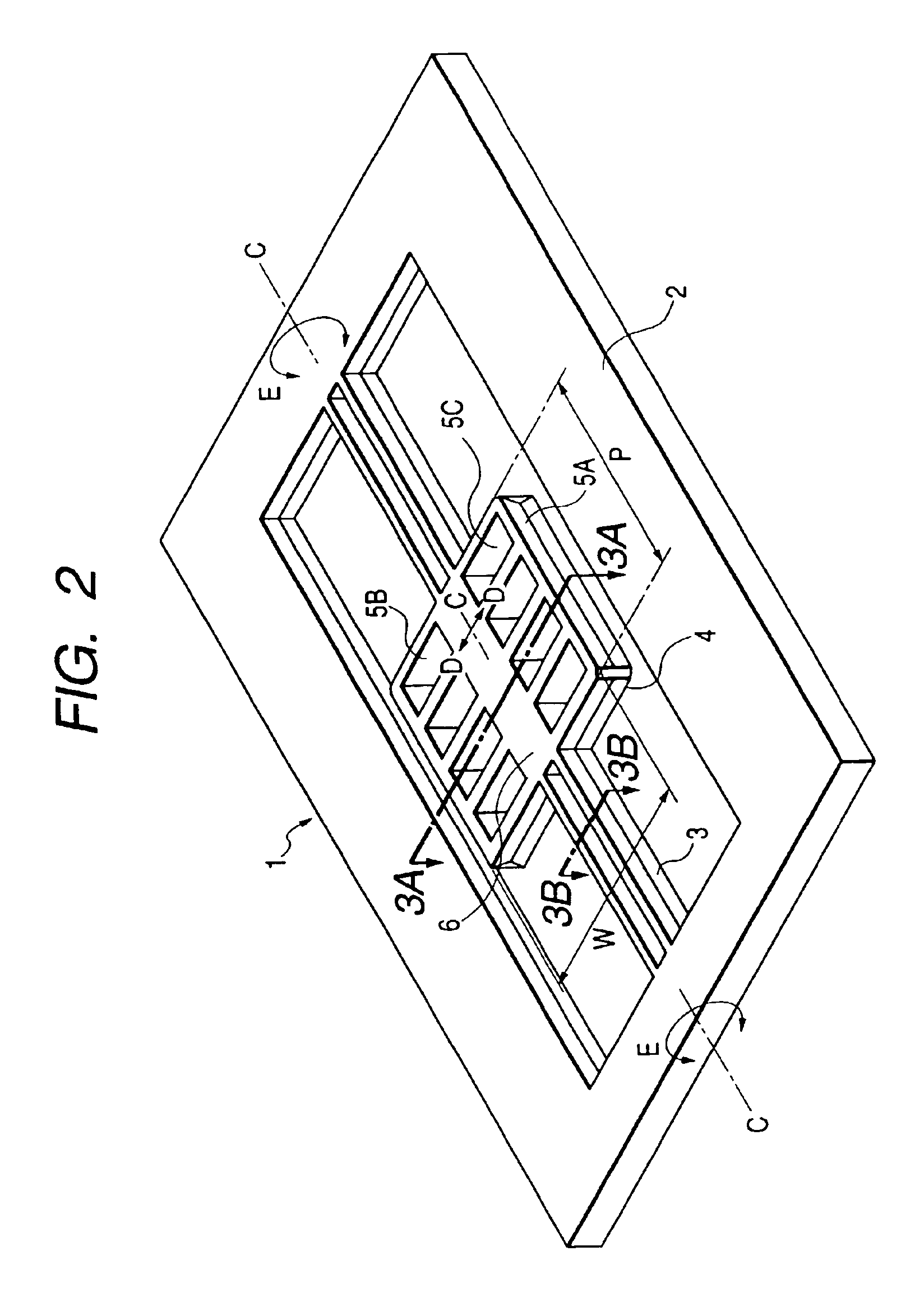
[0054]FIG. 2 is a perspective view showing the structure of a light deflector that is an example of a torsion oscillating member in accordance with a first embodiment of the present invention. Referring to FIG. 2, a light deflector 1 is structured in such a manner that both ends of a movable plate 6 are supported to a support substrate 2 by an elastic support body (torsion spring) 3 corresponding to a torsion oscillating motion shaft. The torsion spring 3 supports the movable plate 6 so as to be torsion-oscillatable elastically in directions E, that is, in both of a clockwise direction and a counterclockwise direction with a shaft C (that is, the torsion axis) as a center. Also, one surface of the movable plate 6 forms a reflection surface 4 (a back side of the drawing and not shown), and deflects an incident light that enters the reflection surface 4 by a given displacement angle due to the torsion of the movable plate 6 in the direction E. Because the movable pla...

Example

(Second Embodiment)

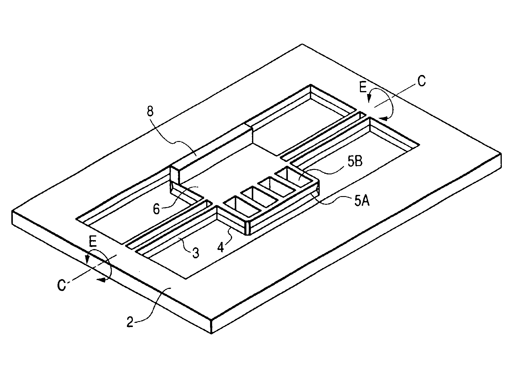
[0082]FIG. 8 is a perspective view showing the light deflector in accordance with a second embodiment of the present invention. A difference of FIG. 8 from FIG. 2 resides in that a recessed portion for reducing the inertia moment is formed on only one side of the movable plate 6 through the torsion axis, and a movable core 8 that is a part of the actuator is disposed at a side where the recessed portion of the movable plate 6 is not formed. Other structures are identical with those in FIG. 2. The movable core 8 is made of a soft magnetic-body (for example, Fe—Ni alloy) or a hard magnetic body (for example, Ni—Co—P alloy), and its dimensions are, for example, 200 μm in width, 50 μm in thickness and 1100 μm in length. The movable core 8 is arranged to extend in a direction of the shaft C on one end of the movable plate 6. The movable core 8 is a member different from the movable plate 6 and stuck onto the movable plate 6. Then, a fixed core (so-called electromagnet)...

Example

(Third Embodiment)

[0084]FIG. 9 is a perspective view showing a light deflector in accordance with a third embodiment of the present invention. In FIG. 9, the same parts as those of FIG. 2 are designated by like reference. In a light deflector 21 according to this embodiment, the respective rows of the recessed portions 5A′, 5B′ and. 5C′ are formed on a surface of the movable plate 6 opposite to the reflection surface 4 on both sides of the torsion axis along the axial direction. In this embodiment, the respective recessed portions in a direction perpendicular to the axial direction are designed such that the opening of the recessed portion farther from the shaft is more widened. Also, the support substrate 2, the torsion spring 3 and the reflection surface 4 are identical with those shown in FIG. 2, and the support substrate 2, the torsion spring 3, the movable plate 6, the recessed portions 5A′, 5B′ and 5C′ are integrally formed with each other by single crystal silicon through the...


PUM

PropertyMeasurementUnit
Timeaaaaaaaaaa

Abstract

There is disclosed a light deflector in which both ends of a movable plate is supported to a support substrate by an elastic support portion, a reflection surface is formed on one surface of the movable plate, and the movable plate is torsion-oscillated about a torsion axis of the elastic support portion as a center to deflect an incident light that enters the reflection surface, wherein a recessed portion is formed on at least one side surface of both sides, which is a surface on which the reflection surface is not formed, and between which the torsion axis of the elastic support portion is interposed.

Description

BACKGROUND OF THE INVENTION[0001]1. Field of the Invention[0002]The present invention relates to a light deflector that deflects an incident light, a method of manufacturing the light deflector, an optical device using the light deflector, and a torsion oscillating member.[0003]2. Related Background Art[0004]Up to now, in a mechanical element that requires high-speed operation, its inertia causes a factor that largely impedes a drive speed. In particular, a mechanical element that rotationally oscillates within a given angle is required to reduce an inertia moment. In this case, however, attention is generally paid to a prevention of the rigidity of the driven mechanical element from being deteriorated. For this purpose, there has been widely known a method in which the mechanical element is of a hollow structure, and a method of fixing a reinforcement material (hereinafter referred to as “rib”).[0005]By the way, in recent years, with the development of the microelectronics represen...

Claims


Application Information

Patent Timeline
IPC IPC(8): G02B26/08G02B7/182B41J2/44B81B3/00B81C1/00G02B26/10G02F1/29
CPCG02B7/1821G02B26/085Y10S359/90G02F1/29
Inventor KATO, TAKAHISAYAGI, TAKAYUKISHIMADA, YASUHIROFURUKAWA, YUKIO
Owner CANON KK
Why Eureka
Try Eureka