Modal variable valve actuation system for internal combustion engine and method for operating the same

a variable valve and internal combustion engine technology, applied in the direction of valve drives, machines/engines, non-mechanical valves, etc., can solve the problems of affecting the performance of the engine, the extra mechanism and the cam take up valuable engine space, and the engine cannot be fully integrated into the exhaust cam profile, etc., to improve the exhaust emissions, simple and inexpensive manufacturing, and improve the power density and fuel economy

Active Publication Date: 2005-08-09
JENARA ENTERPRISES
View PDF18 Cites 53 Cited by
  • Summary
  • Abstract
  • Description
  • Claims
  • Application Information

AI Technical Summary

Benefits of technology

[0082]The radial clearance 177 between the lower lifter body 172 and the upper lifter body 176 permits the hydraulic fluid to gradually leak out of chamber 184 with continued upward pressure of the exhaust valve 15 as the cylinder pressure builds up. This permits the exhaust valve 15 to close near the end of the compression stroke as seen at 114 in FIG. 4 due to the leakage of the hydraulic fluid from the chamber 184 through the radial clearance 177. The lost hydraulic fluid is refilled on every engine cycle, thus resetting the hydraulic extension device 170a of the exhaust rocker assembly 124 before the next engine cycle. Therefore, sizing of the radial clearance 177 between the lower lifter body 172 and the upper lifter body 176 allows the hydraulic fluid to leak out of the chamber 184 of the extension device 170a at a predetermined rat

Problems solved by technology

This fixed lift, duration and timing of the valve events results in compromise among the competing performance factors of engine power density, fuel economy and exhaust emissions.
The EGR provided for positive power is not compatible with engine braking, so a braking lobe cannot be included on the exhaust cam profile.
This extra mechanism and cam takes up valuable space in the engine and is a significant added cost.
These control systems represent added complexity and cost in return for some extra fine-tuning of specific engine processes.
This creates a blow-down of the compressed cylinder gas and the energy used for compression is not reclaimed.
The result is engine braking, or retarding, power.
A conventional

Method used


Image

  • Modal variable valve actuation system for internal combustion engine and method for operating the same
  • Modal variable valve actuation system for internal combustion engine and method for operating the same
  • Modal variable valve actuation system for internal combustion engine and method for operating the same

Examples


Embodiment Construction

[0025]The preferred embodiments of the present invention will now be described with reference to accompanying drawings.

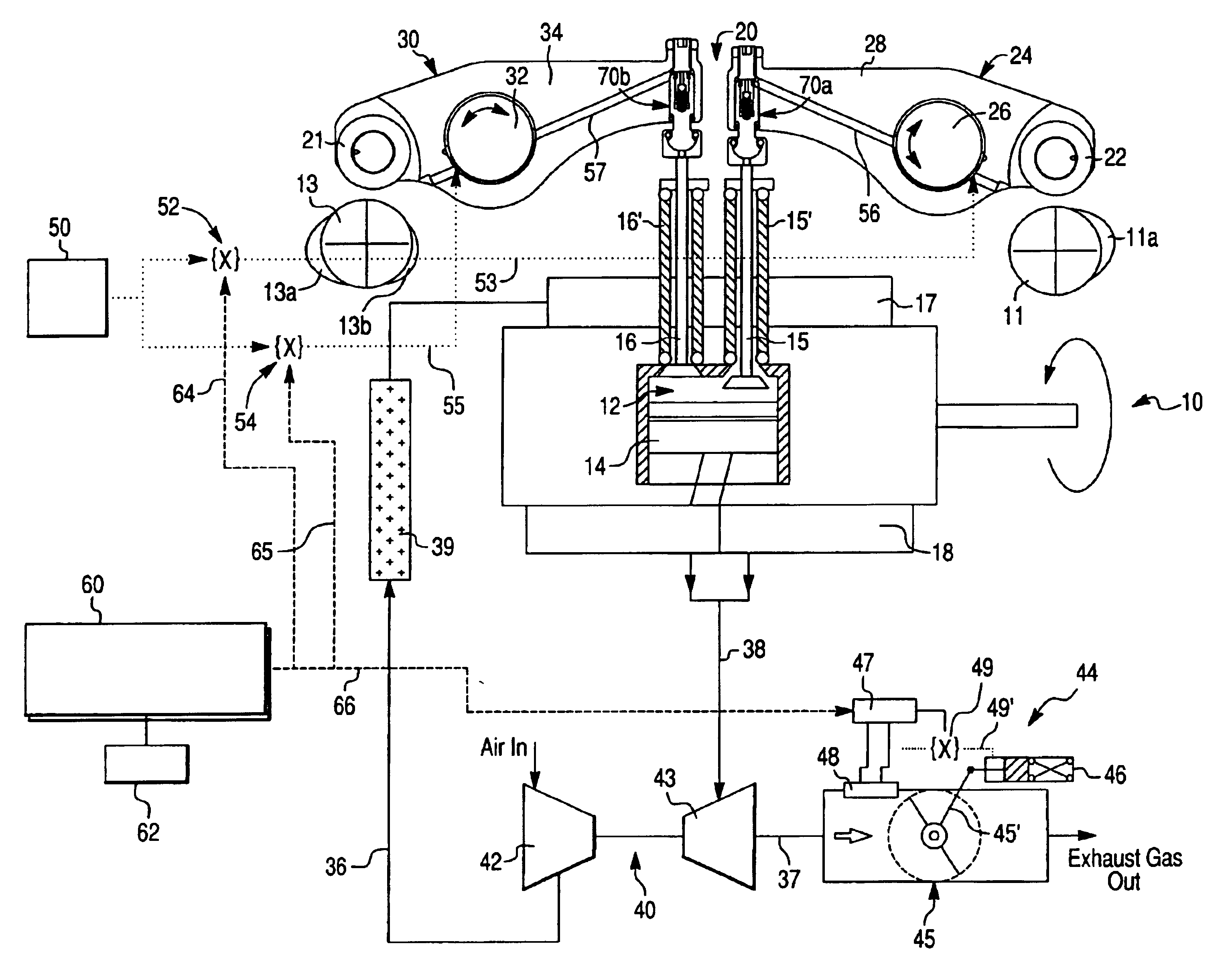
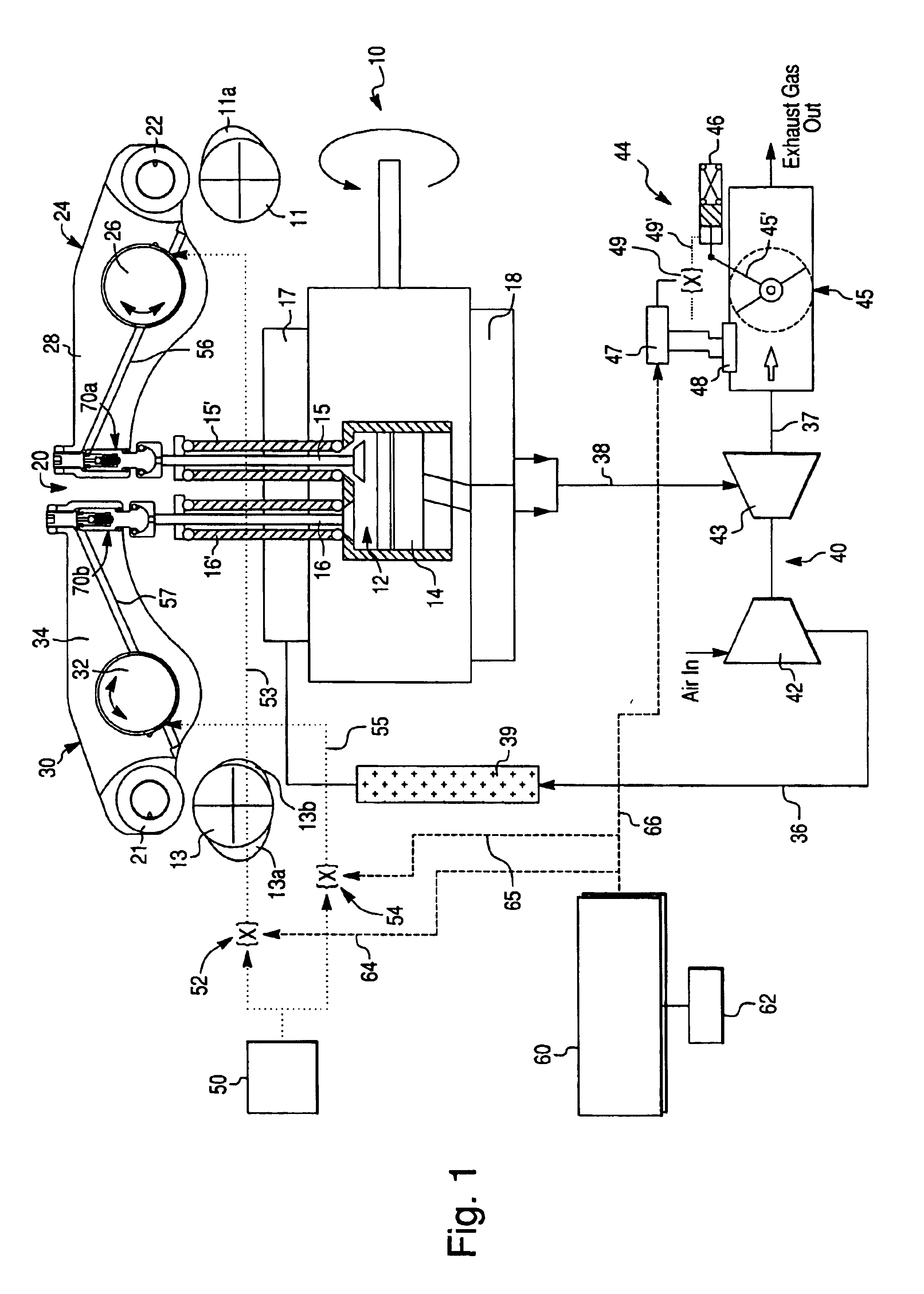
[0026]FIG. 1 schematically depicts a variable valve actuation system 20 of an internal combustion (I.C.) engine 10, preferably a four-stroke diesel engine, comprising a plurality of cylinders. However, for the sake of simplicity, only one cylinder 12 is shown in FIG. 1. Each cylinder 12 is provided with a piston 14 that reciprocates therein. Each cylinder 12 further includes an exhaust valve 15 and an intake valve 16 each provided with a return spring 15′ or 16′, respectively, and a valve train provided for lifting and closing of the exhaust and intake valves 15 and 16. It will be appreciated that each cylinder 12 may have more than one intake valve and / or exhaust valve, but again only one of each is shown for simplicity. The engine also has an intake manifold 17 and an exhaust manifold 18 both in fluid communication with the cylinder 12.

[0027]The valve train of the...


PUM


Abstract

A variable valve actuation system for providing discrete exhaust and intake valve lift profiles for various operating modes of an internal combustion engine. The variable valve actuation system includes exhaust and intake rocker assemblies, exhaust and intake hydraulic extension devices operatively coupling corresponding rocker assemblies with respective engine valves and exhaust and intake control valves for selectively supplying the pressurized hydraulic fluid to the extension devices so as to independently switch them between a pressurized condition and a depressurized condition. The engine further includes an exhaust brake provided to initiate a small lift of the exhaust valve during the engine braking operation while the exhaust extension device maintains the exhaust valve open during a compression stroke for bleeder-compression release braking. The exhaust and intake valves can be adjusted independently to provide combinations of valve lift modes.

Description

CROSS-REFERENCE TO RELATED APPLICATION[0001]This Application claims the benefit under 35 U.S.C. 119(e) of U.S. Provisional Application No. 60 / 452,019 filed Mar. 6, 2003 by Mark A. Israel et al.BACKGROUND OF THE INVENTION[0002]1. Field of the Invention[0003]The present invention relates to apparatuses and methods for controlling actuation of valves of internal combustion engines in general, and, more particularly, to a variable valve actuation system adapted to provide various operating modes of an internal combustion engine including compression release engine braking.[0004]2. Description of the Prior Art[0005]Most commercially available automotive engines operate with fixed valve lift profiles to provide for fresh air intake and exhaust gas discharge. This fixed lift, duration and timing of the valve events results in compromise among the competing performance factors of engine power density, fuel economy and exhaust emissions. Many benefits can be realized if the valve events are ...

Claims


Application Information

Patent Timeline
IPC IPC(8): F01L1/18F01L13/06F01L1/08F01L1/24F02D9/06F02D13/04
CPCF01L1/08F01L1/181F01L1/2411F01L13/06F02D9/06F02D13/04F01L2001/0537F01L2105/00F01L2305/00
Inventor ISRAEL, MARK A.HARTTEY, JOHN P.
Owner JENARA ENTERPRISES
Why Eureka
Try Eureka