High pressure capillary connector

a high-pressure capillary and connector technology, applied in the field of microfluidic systems, can solve the problems of laborious assembly, labor-intensive assembly, and labor-intensive time-consuming and labor-intensive assembly of such devices, and the adhesive bonding is unsuitable for many chemical analysis applications

Inactive Publication Date: 2005-08-09
SANDIA NAT LAB
View PDF48 Cites 142 Cited by
  • Summary
  • Abstract
  • Description
  • Claims
  • Application Information

AI Technical Summary

Benefits of technology

[0017]In a preferred embodiment of the connector, (a) the lower segment has a body cavity that has an interior frustoconical shape, (b) the first member comprises a collet that has a tapered, lower outer portion and which defines a collet aperture that extends from a proximal end to the distal end of the collet with the distal end being in communication with the lower segment aperture of the internal fitting assembly, wherein the collet aperture is defined by an inner wall having one or more slots, and (c) the second member comprises a fastener defining an internal cavity into which the collet is secured wherein the fastener has an upper portion with a fastener aperture that is coaxial with the collet aperture at the proximal end of the collet, wherein the first fluid-bearing conduit can be positioned within the lower segment, collet, and fastener apertures and wherein upon treading the fastener into the internal fitting assembly causes the slots to compress thereby reducing the size of the collet aperture and increasing the force applied to a first fluid-bearing conduit.

Problems solved by technology

Adhesive bonding is unsuitable for many chemical analysis applications because the solvents used attack the adhesive which can lead to channel clogging, detachment of the tubing, and / or contamination of the sample and / or reagents in or delivered to the device.
Furthermore, adhesive bonding results in a permanent attachment of the tubing to the microfluidic device which makes it difficult to change components, i.e., either the microfluidic device or the tubing, if necessary.
Thus assembly, repair and maintenance of such devices become labor and time intensive, a particularly undesirable feature when the microfluidic device is used for high throughput screening of samples such as in drug discovery.
However, such a connection typically is unsuitable for high-pressure applications such as HPLC.
Additionally, pressing the tubing into a port creates high stress loads on the microfluidic device which could lead to fractures of the channels and / or device.
Other methods involved introducing liquids into an open port on the microfluidic device with the use of an external delivery system such as a pipette, but this technique also is undesirable due to the possibility of leaks and spills which may lead to contamination.
Moreover, the use of open pipetting techniques does not permit the use of elevated pressure for fluid delivery such as delivered by a pump, thereby further restricting the applicability of the microfluidic device.

Method used


Image

  • High pressure capillary connector
  • High pressure capillary connector
  • High pressure capillary connector

Examples


Embodiment Construction

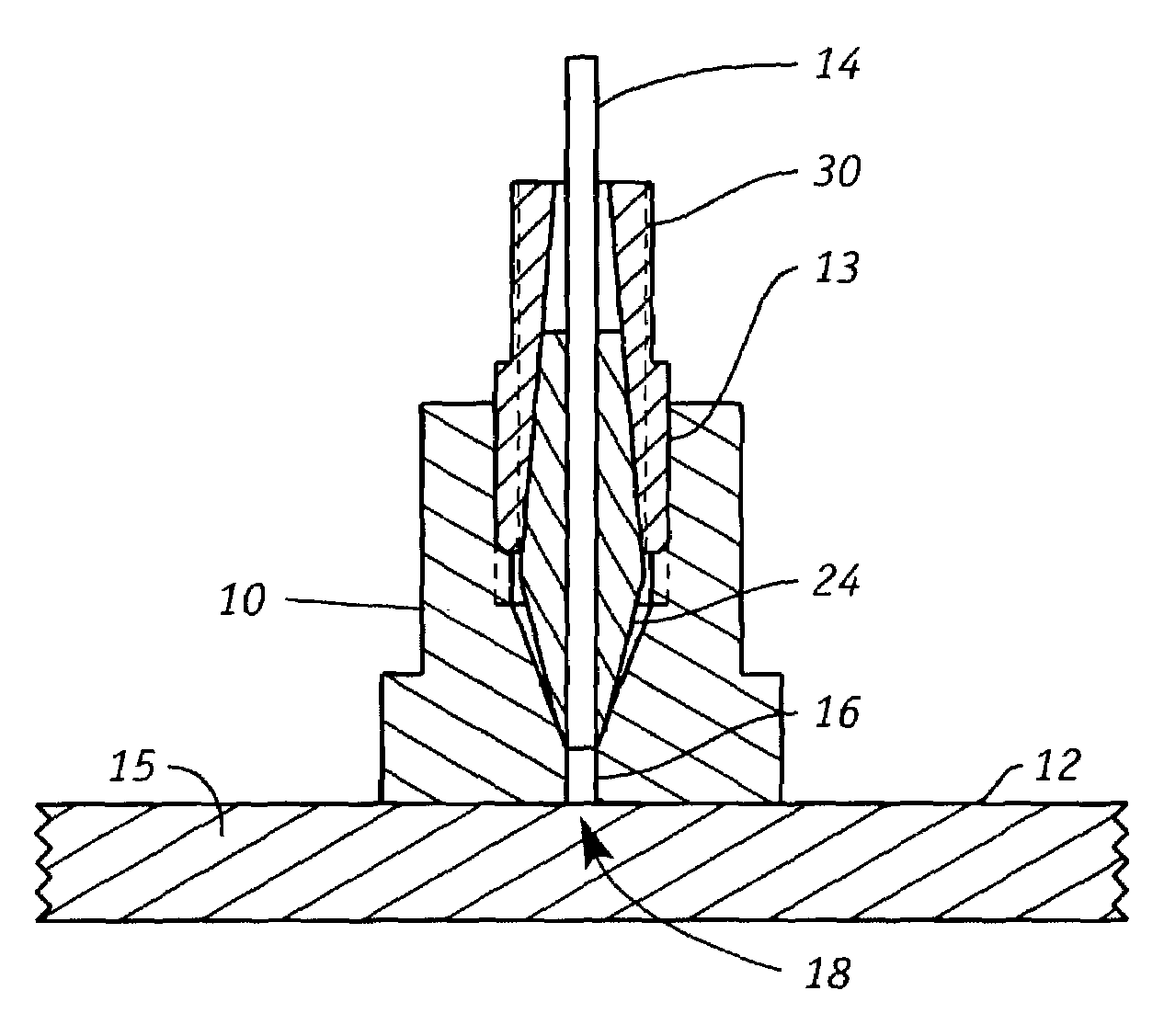
[0025]The capillary connectors of the present invention will be described to connect capillaries to a microscale device, however, it is understood that the use of these connectors is not so limited. The connectors, for example, can be employed as port features in a valve body. In addition, they can be employed for capillary to capillary connections with elbows, tees, crosses, and other channel geometries as further discussed herein.

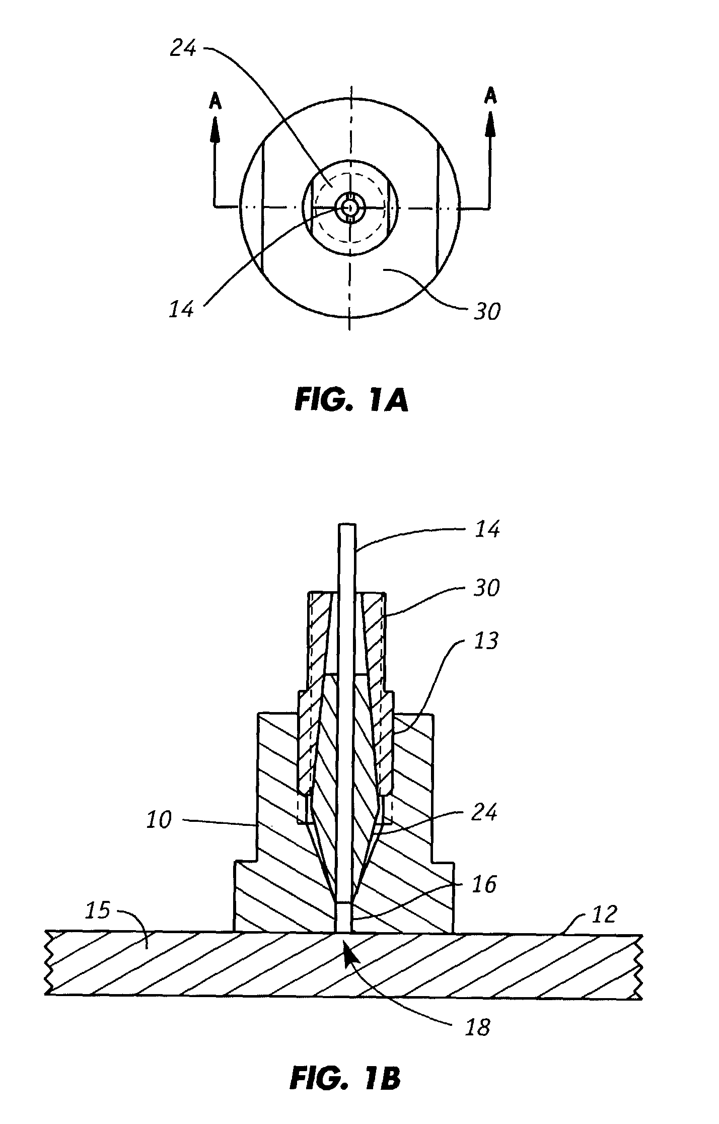
[0026]Referring to FIGS. 1A and 1B, the high pressure capillary connector includes a manifold 10 that is attached to the external surface 12 of a substrate 15, e.g., microscale device, and which has an inlet or outlet port 18 facing external surface 12. The manifold 10 is preferably made of any suitable stiff material that can be bonded, e.g., with epoxy, to external surface 12. Preferred materials include, for example, metal such as stainless steel and ceramics. Alternatively, the compression manifold can be attached to external surface 12 by mechanical ...


PUM

PropertyMeasurementUnit
internal diameteraaaaaaaaaa
pressuresaaaaaaaaaa
outer diametersaaaaaaaaaa

Abstract

A high pressure connector capable of operating at pressures of 40,000 psi or higher is provided. This connector can be employed to position a first fluid-bearing conduit that has a proximal end and a distal end to a second fluid-bearing conduit thereby providing fluid communication between the first and second fluid-bearing conduits. The connector includes (a) an internal fitting assembly having a body cavity with (i) a lower segment that defines a lower segment aperture and (ii) an interiorly threaded upper segment, (b) a first member having a first member aperture that traverses its length wherein the first member aperture is configured to accommodate the first fluid-bearing conduit and wherein the first member is positioned in the lower segment of the internal fitting assembly, and (c) a second member having a second member aperture that traverses its length wherein the second member is positioned in the upper segment of the fitting assembly and wherein a lower surface of the second member is in contact with an upper surface of the first member to assert a compressive force onto the first member and wherein the first member aperture and the second member aperture are coaxial.

Description

[0001]This invention was made with Government support under Contract No. DE-AC04-94AL85000 awarded by the U.S. Department of Energy to Sandia Corporation. The Government has certain rights to the invention.FIELD OF THE INVENTION[0002]The present invention relates generally to microfluidic systems and more particularly to structures which facilitate the introduction of fluids into devices having microfluidic channels.BACKGROUND OF THE INVENTION[0003]Devices for performing chemical analysis have in recent years become miniaturized. For example, microfluidic devices have been constructed using microelectronic fabrication and micromachining techniques on planar substrates such as glass or silicon which incorporate a series of interconnected channels or conduits to perform a variety of chemical analysis such as capillary electrophoresis (CE) and high-performance liquid chromatography (HPLC).[0004]Microfluidic substrates have networks of chambers connected by channels which have mesoscale...

Claims


Application Information

Patent Timeline
Patent Type & Authority Patents(United States)
IPC IPC(8): F16L49/06F16L49/00F16L19/00F16L19/06B01J19/00B01L3/00F04B43/04F04B53/16G01N30/36G01N30/60
CPCB01J19/0093B01L3/502715B01L3/563F04B43/043F04B53/16G01N30/6026B01J2219/0081B01L2200/027B01L2200/0689B01L2300/14G01N30/36G01N30/6078G01N30/6095
Inventor RENZI, RONALD F.
Owner SANDIA NAT LAB
Why Eureka
Try Eureka