
Remediation system

a technology of remediation system and remediation method, which is applied in the direction of cleaning with liquids, separation processes, chemistry apparatus and processes, etc., can solve the problem of not describing a remediation system that allows for separating larger particles, and achieves low manufacturing cost, easy and efficient manufacturing and marketing, and durable and reliable construction

Inactive Publication Date: 2005-08-09
MANN MICHAEL J +1
View PDF14 Cites 12 Cited by
  • Summary
  • Abstract
  • Description
  • Claims
  • Application Information

AI Technical Summary

Benefits of technology

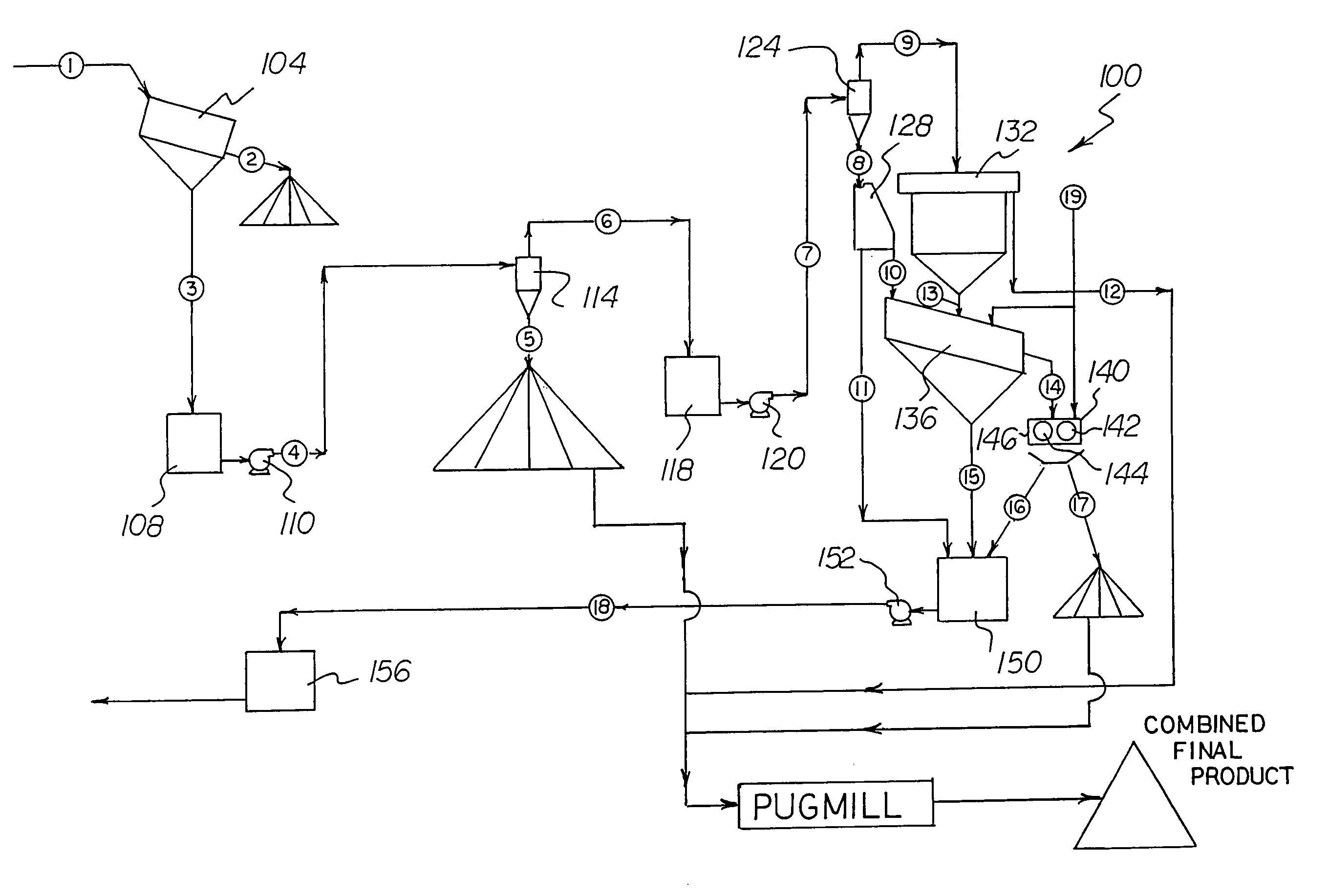
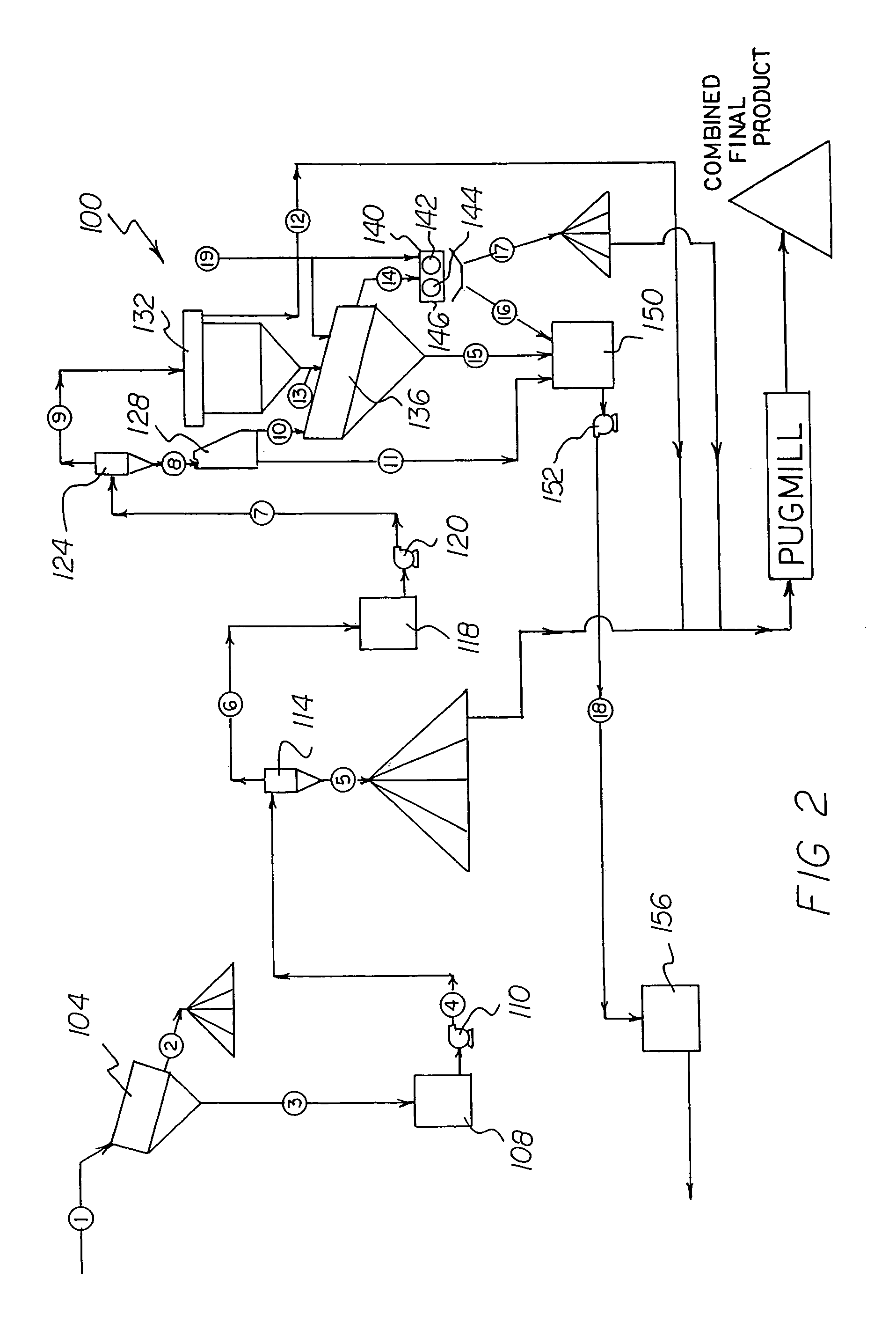
[0025]A horizontal dewatering device is provided. The horizontal dewatering device consists of parallel polyurethane rollers. The rollers are in an enclosed collection box. The horizontal dewatering device is adapted to input the fourteenth stream and a nineteenth stream. The nineteen stream includes reagents to improve the quality of the output seventeenth output stream. This stream may be combined with the sand product (stream 5) and mixed in a pugmill to create a final product. The seventeenth output stream is the secondary product pile and consists of dewatered solids. The extracted water constitutes an output which is a sixteenth stream.
[0032]It is another object of the present invention to provide a new and improved remediation system which may be easily and efficiently manufactured and marketed.
[0033]It is further object of the present invention to provide a new and improved remediation system which is of durable and reliable constructions.
[0034]An even further object of the present invention is to provide a new and improved remediation system which is susceptible of a low cost of manufacture with regard to both materials and labor, and which accordingly is then susceptible of low prices of sale to the consuming public, thereby making such remediation system economically available to the buying public.

Problems solved by technology

While these devices fulfill their respective, particular objectives and requirements, the aforementioned patents do not describe a remediation system that allows for separating larger particles from smaller particiles and dewater the resulting products.

Method used


Image

  • Remediation system
  • Remediation system
  • Remediation system

Examples


Embodiment Construction

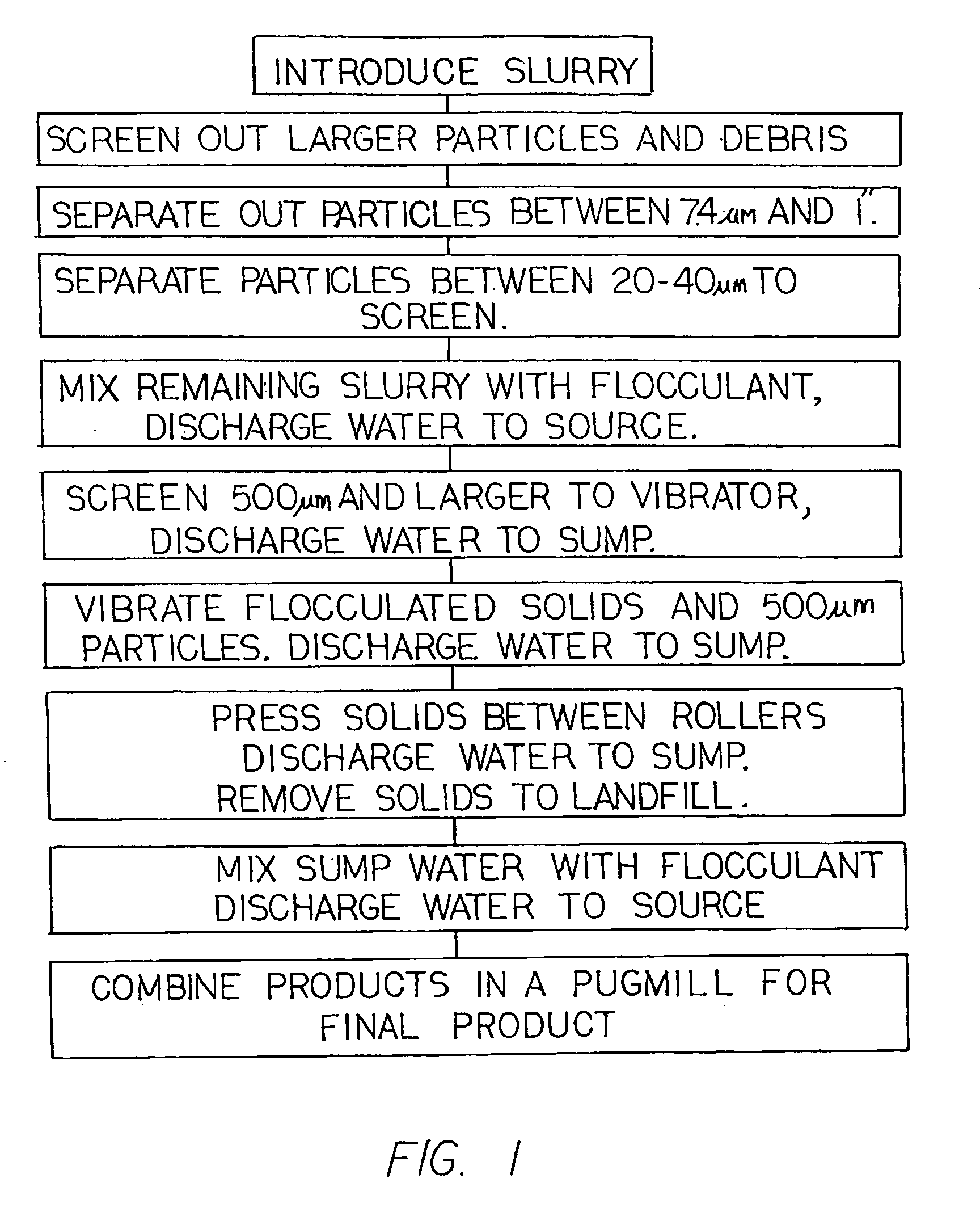
[0042]With reference now to the drawings, and in particular to FIG. 1 thereof, the preferred embodiment of the new and improved remediation system embodying the principles and concepts of the present invention and generally designated by the reference numeral 10 will be described.

[0043]The present invention, the remediation system 100 is comprised of a plurality of components. Such components in their broadest context include a primary scalping screen, a primary sump and a primary pump, a primary large diameter maximum density separator, a secondary sump and a secondary pump, a small diameter maximum density separator, a static sieve screen, a flocculation sump, a vibrating screen, a dewatering device, a tertiary sump and a tertiary pump, a secondary flocculation tank and screens.

[0044]First provided is a primary scalping screen 104. The scalping screen has 1 inch openings. The scalping screen is adapted to receive a first stream 1. The first stream is comprised of a slurry of vario...


PUM

PropertyMeasurementUnit
Lengthaaaaaaaaaa
Lengthaaaaaaaaaa
Lengthaaaaaaaaaa

Abstract

A remediation system comprises a primary scalping screen, a primary pump and sump, a large diameter maximum density separator with flocculant injection ring, a secondary pump and sump, a small diameter maximum density separator with flocculant injection ring, a static sieve screen, a flocculation sump, a vibrating screen, a dewatering device, a tertiary sump and pump, a secondary flocculation tank, and a pugmill. Screens move water and particulates through the components. In this manner larger particles are separated from smaller particles and the particles are further dewatered.

Description

[0001]This application is a continuation-in-part of application Ser. No. 10 / 336,405 filed Jan. 3, 2003 entitled Remediation System, now abandoned.FIELD OF THE INVENTION[0002]This invention relates to soil and sediment remediation, remediation of mining tailings, and the treatment of chemical process sludges. This process utilizes a combination of screening, separation using hydrocyclones, sand dewatering, chemical flocculation, and fines dewatering on fixed and vibrating screens. This invention is unique because the fine-grained fraction can be dewatered to a dry solids concentration of greater than 40 percent without the use of pressure filtration equipment, and provides for a combined end-use product.[0003]Contaminated soil and sediments are a serious problem worldwide. Most countries now have strong regulations that prohibit the development and use of properties with contaminated soil. When these properties are cleaned-up, commonly referred to as remediated, the handling of the s...

Claims


Application Information

Patent Timeline
IPC IPC(8): B01D21/01B09C1/02B09C1/00B01D21/00B03B9/00C02F1/52
CPCB01D21/01B01D21/283B03B9/00B09C1/00C02F1/5281
Inventor MANN, MICHAEL J.HAZEN, JAMES J.
Owner MANN MICHAEL J
Learn More