Laser machining method and apparatus

a laser beam and machining technology, applied in the direction of photomechanical treatment originals, manufacturing tools, instruments, etc., can solve the problems of etching gas which meets the requirements for pattern correction operations, the edge shape of laser beam-machined parts to be degraded in linearity, and the development pattern width is different from the predetermined width, so as to reduce the cost of introducing the apparatus and maintain the effect of high safety and maintenance cos

Inactive Publication Date: 2005-08-09
LASERFRONT TECH
View PDF15 Cites 8 Cited by
  • Summary
  • Abstract
  • Description
  • Claims
  • Application Information

AI Technical Summary

Benefits of technology

[0016]The invention provides a laser machining method using a halogenated hydrocarbon represented by ethyl iodide as an etching gas, and a configuration in which the surface to be etched of a substrate is directed downward. Thereby, this method has a high level of safety in the respects of corrosivity, toxicity and flammability and therefore does not require complicated and expensive components to be used, thus reducing cost for introducing the apparatus and maintenance cost. Further, for the quality of machining, this method can provide high-quality correction in which damages in the substrate are limited to an extremely small degree and no bumps are formed on the edges of machined portions.
[0017]Also, applying the structure of the gas enclosure according to the invention to apparatuses of laser etching machining and laser CVD machining, it is possible to reduce the manufacturing cost of the apparatuses, and by increasing the upper limit of the velocity of flow of source gas allowed at the laser beam irradiation portion, machining conditions can be optimized over wide range and also the gap distance between the gas enclosure and the substrate can be made much larger than conventional methods, greatly reducing the probability of accidents scratching the surface to be machined. Thereby, the invention can provide a highly practical laser machining apparatus.

Problems solved by technology

However, laser correction methods using the conventional laser vaporization method require that laser irradiation instantaneously heat a pattern film to be removed to a high temperature of several thousand degrees Celsius, and this causes a problem that the irradiation can dig holes in the substrate surface with a pattern film adhering thereon even if the substrate is a high-temperature-resistant substrate such as quartz.
For this reason, when this mask is used in the actual exposure process, the damages cause changes in the phase of the light for exposure, which can result in a developed pattern width different from the predetermined width.
In order to decrease the depth of damages, laser power for correcting patterns may be lowered relative to the optimum condition but this causes a problem that the edge shape of laser beam-machined portions to be degraded in linearity.
However, in the case of photomasks using chromium as a pattern material, which is generally chemically and thermally high resistant, there has been no proposal of etching gas which meets requirements for use in pattern correction operations, such as easy handling, proper reaction speed, and ability to make reaction products having a high vapor pressure.
However, it is very difficult to construct such dual gas flow paths concentrically arranged around the laser irradiation portion in the gas enclosure, within the range of a usual gap distance of only about 1 mm, between the substrate surface and the gas enclosure, the distance depending on the operating range of the objective lens.
Thus, this causes problems of high fabricating cost and low construction yield of the gas enclosure.
In a high precision laser machining apparatus, the high resolution of the apparatus requires a shorter operating range, so that it is no longer possible to ensure a space for the gas enclosure.
This causes a problem that a high precision machining apparatus cannot have such a gas window.
In this case, the gas shield effect of the blowoff port is broken, resulting in problems such as the leakage of the source gas into the surroundings, the mixing of air, and the like.

Method used


Image

  • Laser machining method and apparatus
  • Laser machining method and apparatus
  • Laser machining method and apparatus

Examples


first embodiment

[0043]Further, in the invention described above, the descriptions have been done for the cases in which the reaction of laser etching and the reaction of laser CVD are performed individually. The source gas feeding unit is configured so as to feed both a source gas for CVD and a source gas for etching, whereby the methods of machining can be switched by switching between the gases according to the type of defect to be corrected. In this case, since one apparatus allows both machining processes of film-forming and film-removing, this allows the total throughput required for correction to be high speed, providing an advantage of higher practicality.

second embodiment

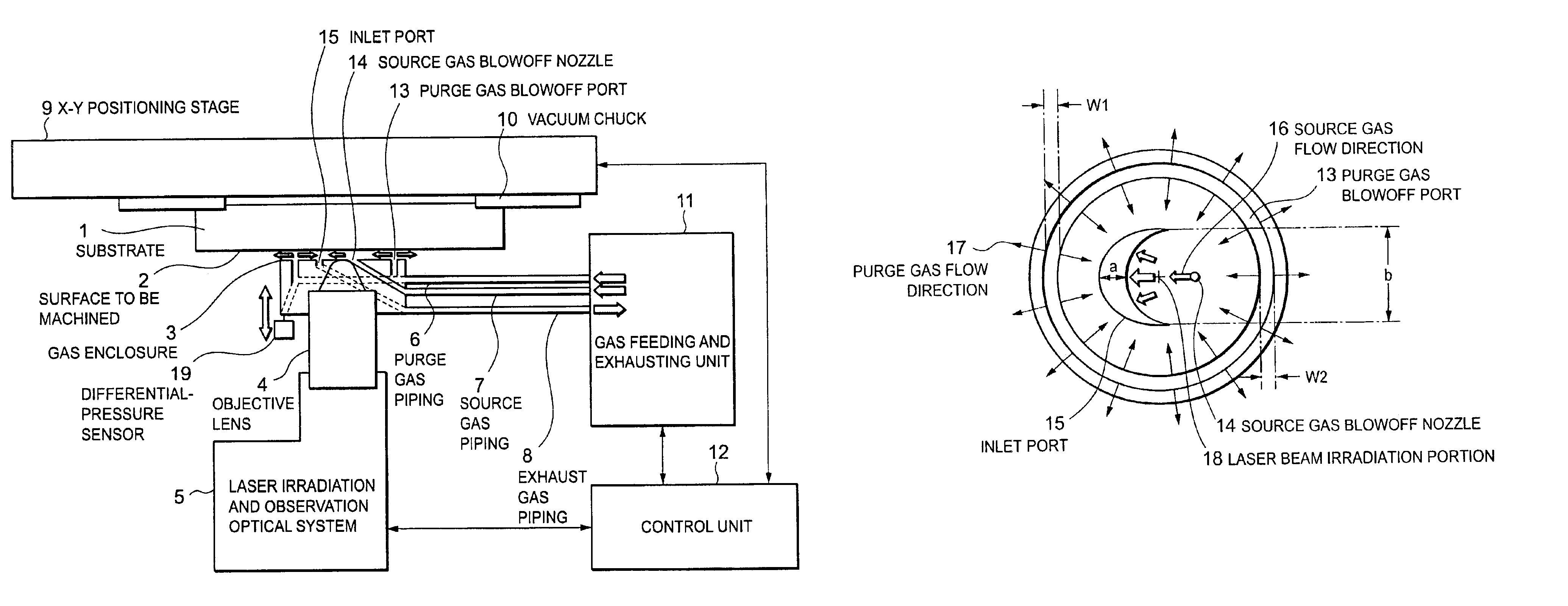
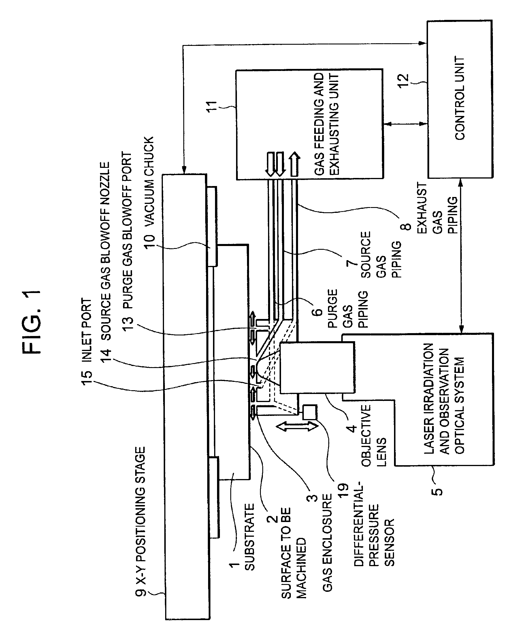
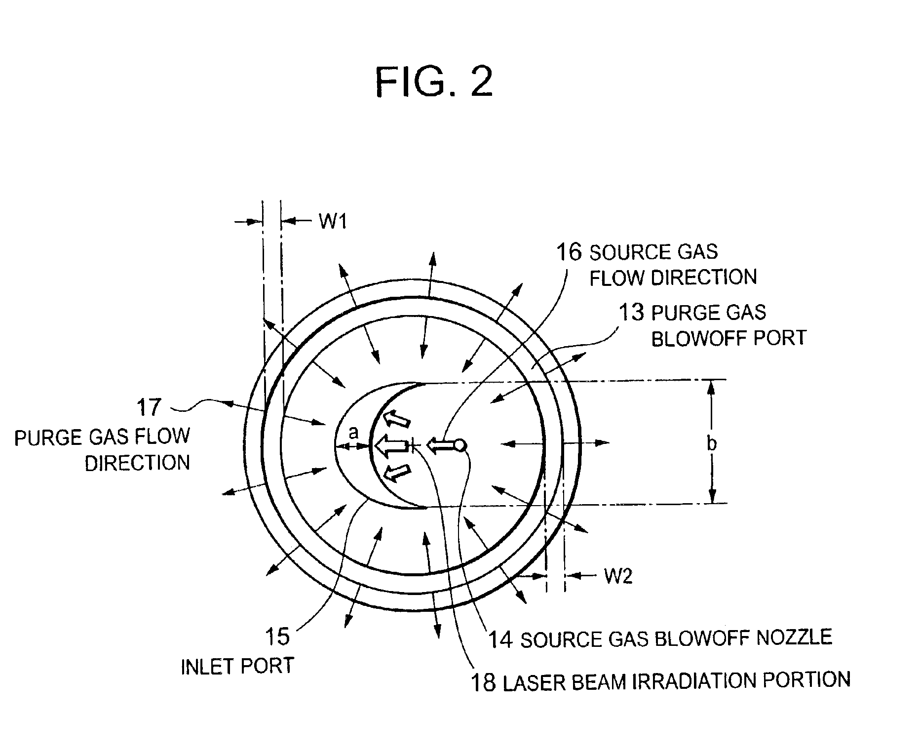
[0044]Next, as the invention, an apparatus performing film-forming reaction by laser CVD is shown in FIG. 3, wherein the structure of the gas enclosure shown in FIG. 2 is used and the surface to be machined of the substrate is directed upward and thus irradiated with a laser beam from above. In this case, since the substrate has the surface to be machined directed upward, there is an advantage that the substrate can be easily held on the X-Y positioning stage. Further, even if the velocity of flow of source gas is made higher at the laser irradiation portion as compared to the conventional gas enclosure provided with dual concentric openings for suction and blowoff, of purge gas, the leakage of the source gas into the surroundings does not occur. Therefore, higher velocity of flow of the source gas can suppress the adherence of fine particles depositing on the surrounding area of the CVD film, improving the quality of correction.

[0045]Further, in this structure, by introducing laser...


PUM

PropertyMeasurementUnit
Widthaaaaaaaaaa

Abstract

In a laser machining method for removing remaining defects on a photomask, there has been problems to be resolved that damage is formed at the portion of the substrate where the defect has been removed, thus resulting in degraded quality of machining. In a laser machining method for removing remaining defects on a photomask by a method of laser machining, the remaining defects are removed by using a configuration in which irradiation with a laser beam is performed from below with a to-be-machined surface directed downward, and irradiation with a laser beam in an atmosphere containing a halogenated hydrocarbon gas (as an example, ethyl iodide).

Description

BACKGROUND OF THE INVENTION[0001]1. Field of the Invention[0002]The invention relates to a method of laser machining for correcting pattern defects on photomasks and liquid crystal substrates, and a laser machining apparatus using the method.[0003]2. Description of the Related Art[0004]One of prior art laser machining apparatuses for correcting pattern defects on photomasks and liquid crystal substrates is disclosed in Japanese Patent Laid-Open No. 2002-62637. In the method for correcting pattern defects disclosed by this application, a substrate is irradiated with a laser beam while its surface to be machined is directed downward thereby removing defects on the substrate by laser vaporization. In this method disclosed, the substrate surface can be observed without lowering the resolution of an optical system for observing it while the substrate surface is being irradiated with a laser beam. Further, since fine particles produced by the laser vaporization can fall down by gravitatio...

Claims


Application Information

Patent Timeline
IPC IPC(8): C23F1/02C23F1/08G03F1/00B23K26/12G03F1/72H01L21/302
CPCB23K26/03B23K26/0853B23K26/12B23K26/126B23K26/127C23F1/02C23F1/08G03F1/72B23K26/1405B23K26/142G03F1/74
Inventor MORISHIGE, YUKIO
Owner LASERFRONT TECH
Why Eureka
Try Eureka