Holographic illuminator for synchrotron-based projection lithography systems

a technology of holographic illumination and projection lithography, which is applied in the field of microelectronics, can solve the problems of increasing the scattering angle significantly above the angle, incoherent light at a particular illumination angle with respect to light at all other illumination angles, and the conventional method of fabricating euv diffusers, etc., to reduce the potential high-angle scattering and multi-layer reflectivity loss problems, reduce the scattering angle, and eliminate the intrinsic roughness

Inactive Publication Date: 2005-08-09
EUV
View PDF22 Cites 9 Cited by
  • Summary
  • Abstract
  • Description
  • Claims
  • Application Information

AI Technical Summary

Benefits of technology

[0013]The major difficulty with conventional diffuser methods lies in fabricating the EUV diffuser. Intrinsic roughness caused by the processing involved in creating the custom relief substrate, tends to increase the scattering angle significantly above the angle desired for typical EUV systems. Most EUV systems have numerical apertures ranging from 0.1 to 0.3; assuming a conventional coherence factor of 0.7 and magnification of 4, the diffuser would ideally have a scattering numerical aperture of approximately 1 degree. Uncontrolled roughness in a diffuser will typically scatter light over an angle of 10 degrees, leading to a two-dimensional loss factor of about 100 due to area effects. An additional loss factor of approximately 10 or larger would also be expected due to loss of multilayer reflectivity. These losses would have a dramatic effect on the optical throughput of the system.
[0

Problems solved by technology

Additionally, light at a particular illumination angle is incoherent with respect to light at all other illumination angles.
The major difficulty with conventional diffuser methods lies in fabricating the EUV diffuser.
Intrinsic roughness caused by

Method used


Image

  • Holographic illuminator for synchrotron-based projection lithography systems
  • Holographic illuminator for synchrotron-based projection lithography systems
  • Holographic illuminator for synchrotron-based projection lithography systems

Examples


Embodiment Construction

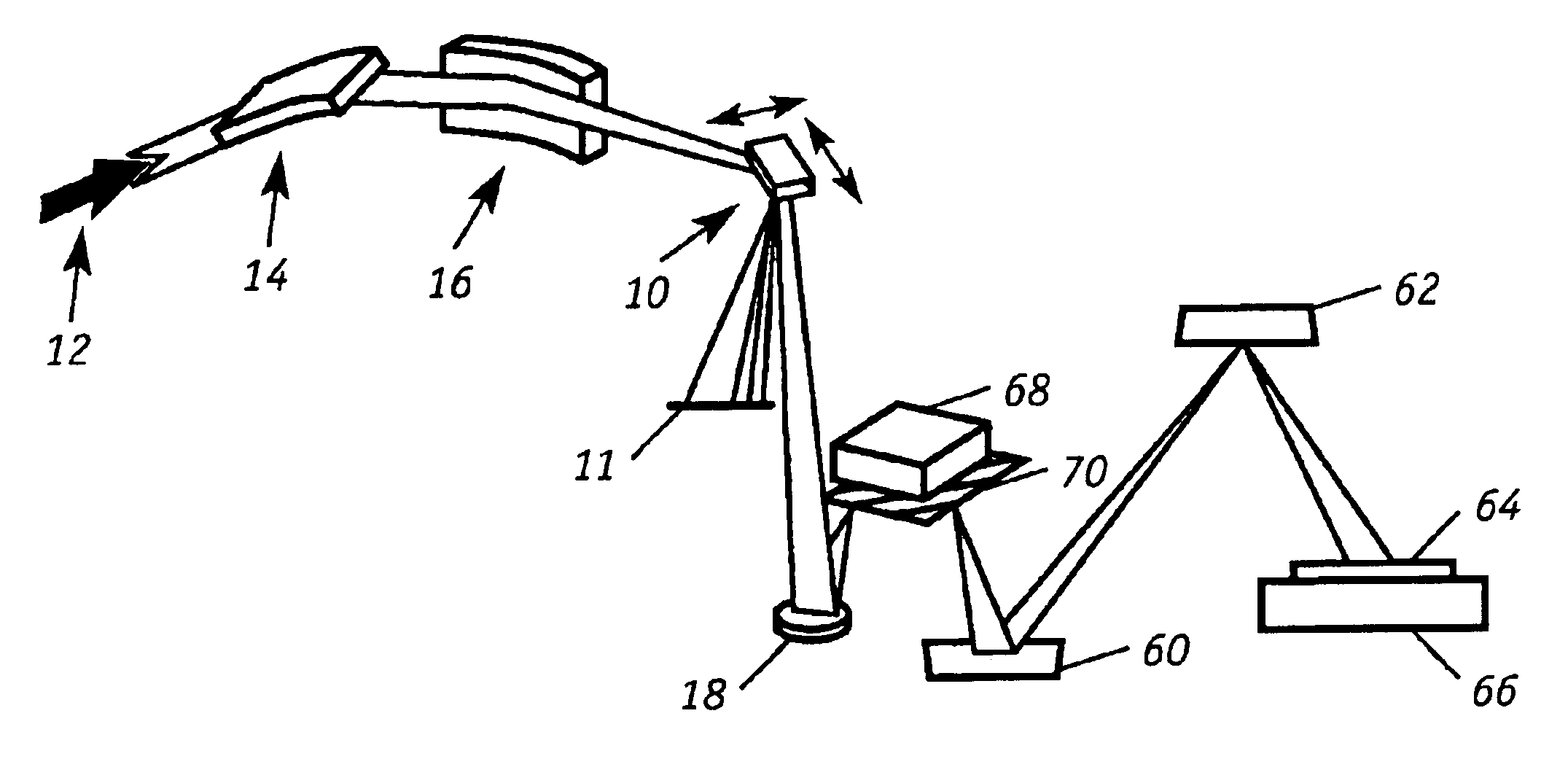
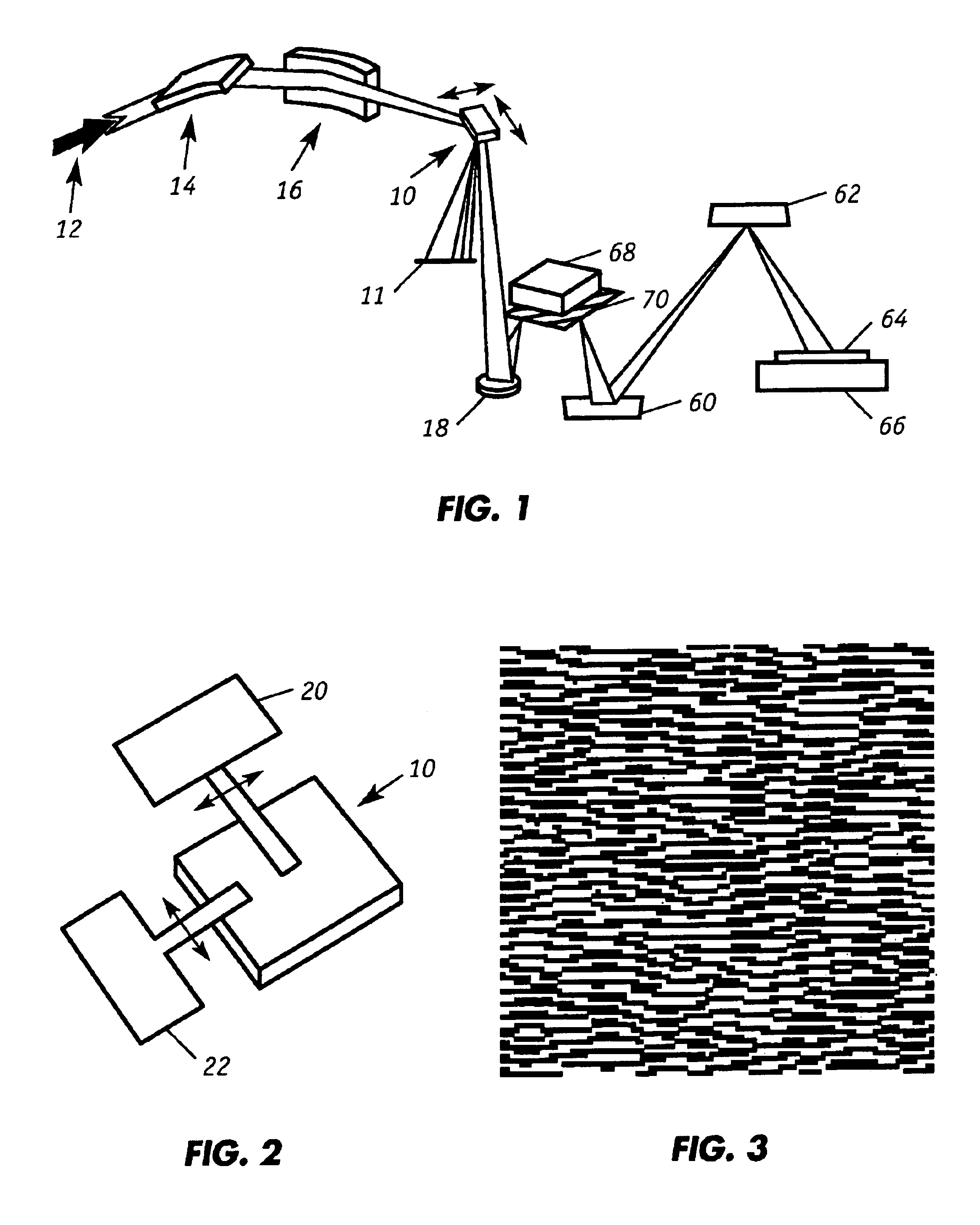
[0029]FIG. 1 shows a schematic of the preferred embodiment of the illuminator wherein an effectively coherent synchrotron radiation beam 12 is delivered to moving holographic diffuser 10 by way of conventional beamline optics 14,16. The moving holographic diffuser redirects the beam towards relay mirror 18. As shown in FIG. 2, the movement of holographic diffuser 10 can be controlled by translation mechanisms 20, 22 such that the holographic diffuser 10 is able to be translated linearly in the plane of the holographic surface. The speed of this translation should be rapid enough such that many, preferably about 1000 or more, correlation lengths of the holographic diffuser are spanned during the imaging systems exposure, or integration, time. These translation mechanisms could consist of commercially available x-y stages. For a typical EUV application with a 0.20 numerical aperture projection lithography optic (resolution approximately 40 nm), a desired partial coherence (sigma) of 0...


PUM


Abstract

The effective coherence of a synchrotron beam line can be tailored to projection lithography requirements by employing a moving holographic diffuser and a stationary low-cost spherical mirror. The invention is particularly suited for use in an illuminator device for an optical image processing system requiring partially coherent illumination. The illuminator includes: (1) a synchrotron source of coherent or partially coherent radiation which has an intrinsic coherence that is higher than the desired coherence, (2) a holographic diffuser having a surface that receives incident radiation from said source, (3) means for translating the surface of the holographic diffuser in two dimensions along a plane that is parallel to the surface of the holographic diffuser wherein the rate of the motion is fast relative to integration time of said image processing system; and (4) a condenser optic that re-images the surface of the holographic diffuser to the entrance plane of said image processing system.

Description

[0001]The U.S. Government has certain rights in this invention pursuant to Contract No. DE-AC03-76SF00098 between the United States Department of Energy and the University of California for the operation of the Lawrence Berkeley National Laboratory.FIELD OF THE INVENTION[0002]EUV lithography (EUVL) is an emerging technology in the microelectronics industry. It is one of the leading candidates for the fabrication of devices with feature sizes of 70 nm and smaller. Synchrotron radiation facilities provide a convenient source of EUV radiation for the development of this technology. This invention relates to techniques for generating partially coherent radiation and particularly for converting effectively coherent radiation from a synchrotron to partially coherent extreme ultraviolet radiation suitable for projection photolithography.BACKGROUND OF THE INVENTION[0003]In general, lithography refers to processes for pattern transfer between various media. A lithographic coating is generall...

Claims


Application Information

Patent Timeline
IPC IPC(8): G03F7/20G02B5/32
CPCG02B5/32G03F7/70075G03F7/70091G03F7/70158G03F7/70583
Inventor NAULLEAU, PATRICK P.
Owner EUV
Why Eureka
Try Eureka