
Control device for spark-ignition engine

a control device and spark ignition technology, applied in the direction of electric control, machines/engines, combustion air/fuel air treatment, etc., can solve the problems of product cost, disadvantageous provision of lean nox catalyst, lean nox catalyst is susceptible to sulfurization poisoning, etc., to prevent deterioration of emission-cleaning performance

Inactive Publication Date: 2005-08-16
MAZDA MOTOR CORP
View PDF13 Cites 2 Cited by
  • Summary
  • Abstract
  • Description
  • Claims
  • Application Information

AI Technical Summary

Benefits of technology

[0013]In light of the foregoing, it is an object of the invention to provide such a control device for a spark-ignition engine that can properly switch the engine between a normal operation mode and a special operation mode while preventing deterioration of emission-cleaning performance during a transition period in which gas flow paths of the engine are switched.
[0014]The inventors of the present invention have intensively studied a phenomenon that the amount of NOx emissions can be decreased by combustion caused by compression ignition. Through this study, the inventors have reached an understanding that the temperature of fresh air introduced from preceding cylinders into following cylinders can be increased by interrupting combustion in the preceding cylinders and passing the fresh air through the preceding cylinders which retain a high-temperature atmosphere and, as a consequence, it becomes possible to produce compression ignition in the following cylinders and thereby prevent deterioration of emission-cleaning performance.
[0017]The aforementioned control devices of the invention control the engine to produce combustion in the special operation mode when the engine is in the part-load range. When the engine is controlled in the special operation mode in the part-load range, a substantial fuel economy improvement effect is obtained in the preceding cylinders as a result of an improvement in thermal efficiency achieved by the lean burn operation and a reduction in pumping loss in the preceding cylinders. In the following cylinders, on the other hand, the mixture produced by supplying fuel to the burned gas having a high air-fuel ratio introduced from the preceding cylinders is combusted, so that a fuel economy improvement effect is obtained due at least to a reduction in pumping loss in the following cylinders. In the special operation mode, the amount of NOx emissions from the preceding cylinders is kept to a relatively low level as the mixture having a significantly high air-fuel ratio is combusted in the preceding cylinders, whereas NOx emissions from the following cylinders are sufficiently suppressed as the burned gas is introduced from the preceding cylinders to create a condition equivalent to what would occur when a great deal of exhaust gas is introduced by EGR operation in the following cylinders. These features of the invention are advantageous for improving the quality of emissions.
[0018]When the engine is switched between the normal operation mode in which the gas flow paths are set to the independent cylinder configuration and the special operation mode in which the gas flow paths are set to the two-cylinder interconnect configuration, the control device temporarily selects the transitional operation mode in which the gas flow paths are set to the two-cylinder interconnect configuration. Specifically, the gas flow paths are switched to the two-cylinder interconnect configuration when the engine is switched from the normal operation mode to the special operation mode, whereas the gas flow paths are left in the two-cylinder interconnect configuration when the engine is switched from the special operation mode to the normal operation mode, and the control device interrupts combustion in the preceding cylinders in the transitional operation mode. In transitional operation mode, fresh air to be introduced into the following cylinders is heated in the preceding cylinders which retain a high-temperature atmosphere as combustion has been produced in the preceding cylinders until interrupted immediately before. Since the temperature of the fresh air is increased in this way, it becomes possible to produce compression ignition in the following cylinders. As the mixture in the following cylinders is combusted by the compression ignition in the transitional operation mode, NOx emissions from the following cylinders can be sufficiently suppressed during a period of operation mode transition. It is therefore possible to properly switch the engine between the normal operation mode and the special operation mode while preventing deterioration of the emission-cleaning performance regardless of the value of the air-fuel ratio of the mixture.
[0019]Moreover, since the control device produces combustion only in the following cylinders upon interrupting combustion in the preceding cylinders in the transitional operation mode, it is possible to combust the mixture by the compression ignition in a reliable fashion even in the period of operation mode transition during which the quantity of fresh intake air is unstable.

Problems solved by technology

The provision of the lean NOx catalyst is disadvantageous from the viewpoint of product cost.
Moreover, the lean NOx catalyst is susceptible to poisoning by sulfurization if the fuel used has a high sulfur content.
All such problems of the conventional engine would jeopardize fuel economy improvement effects of the lean burn operation.
This makes it possible to prevent too late combustion which does not produce any effective work.
In an ordinary spark-ignition engine, however, the temperature and pressure in the combustion chamber do not increase to such levels that are high enough to produce compression ignition at about a top dead center in the compression stroke.
It has conventionally been difficult, however, to increase the temperature or the pressure in the combustion chamber to a level high enough to produce compression ignition in a part-load range in which the fuel economy must be improved while avoiding knocking (abnormal combustion caused by spontaneous firing of the mixture occurring before propagation of a flame in the combustion chamber) in a high-load range.
In this spark-ignition engine, a problem tends to occur in control operation for switching gas flow paths from the independent cylinder configuration to the two-cylinder interconnect configuration.
The emission-cleaning performance of the engine could deteriorate during a transition period of this gas flow path switching operation.
More particularly, it is so difficult to instantly alter and regulate the quantity of fresh intake air immediately following the gas flow path switching operation, and this poses a problem in controlling the air-fuel ratio which is the ratio of the quantity of fresh intake air to the quantity of fuel (gasoline).
This makes it difficult to clean exhaust gases by using the three-way catalyst alone which has the high emission-cleaning performance at about the stoichiometric air-fuel ratio.
Therefore, the emission-cleaning performance potentially deteriorate in the aforementioned spark-ignition engine.

Method used


Image

  • Control device for spark-ignition engine
  • Control device for spark-ignition engine
  • Control device for spark-ignition engine

Examples


Embodiment Construction

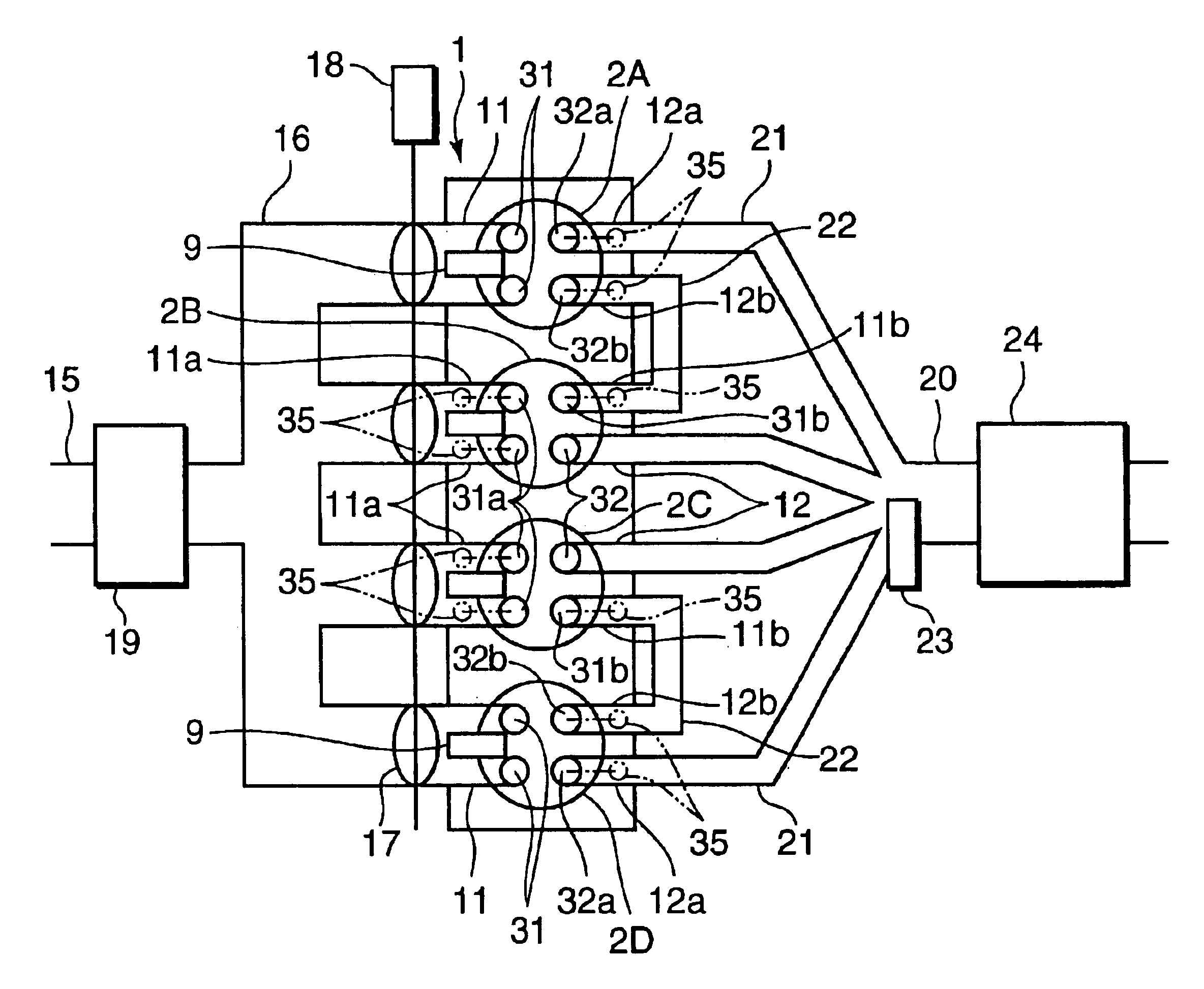
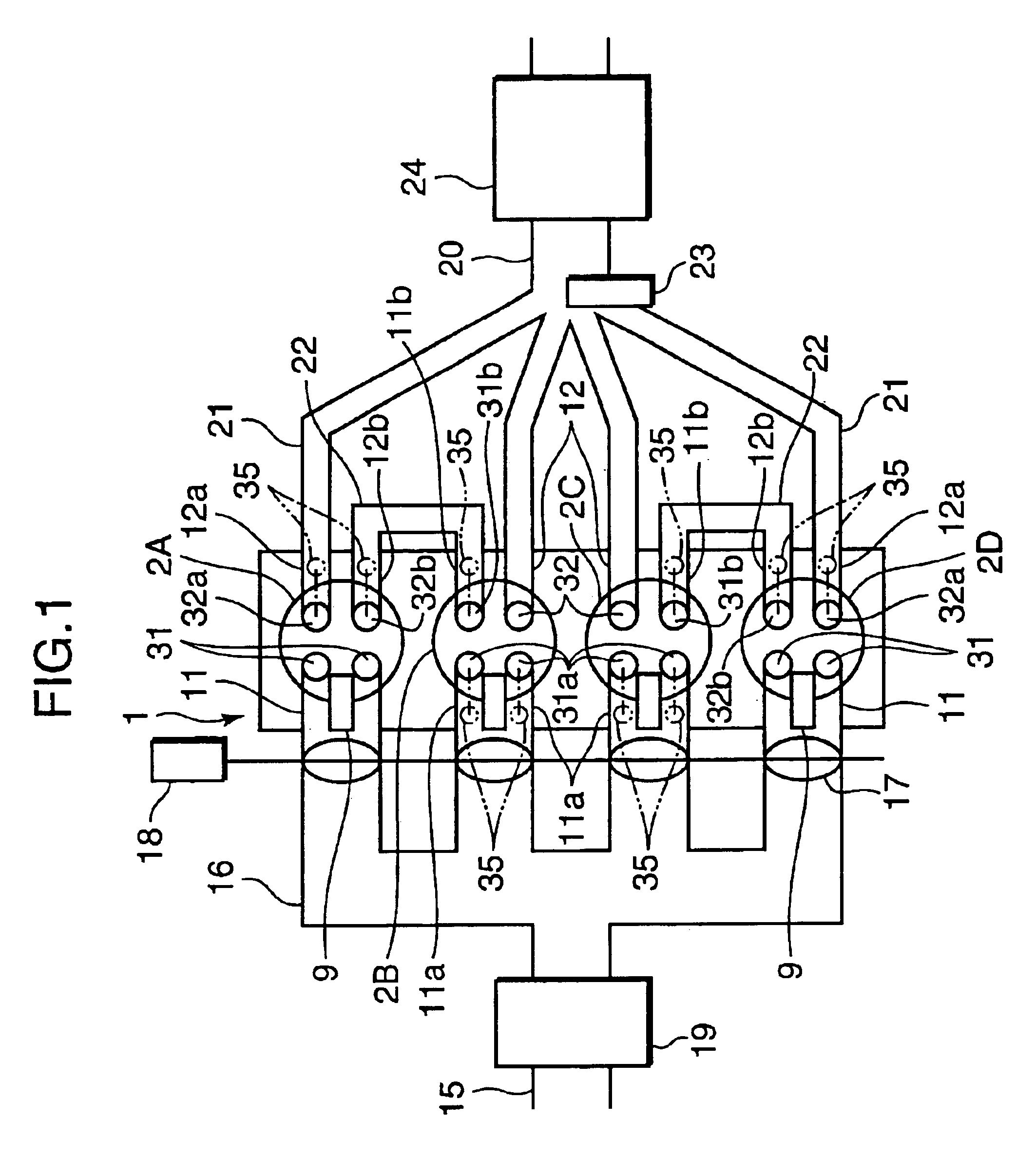
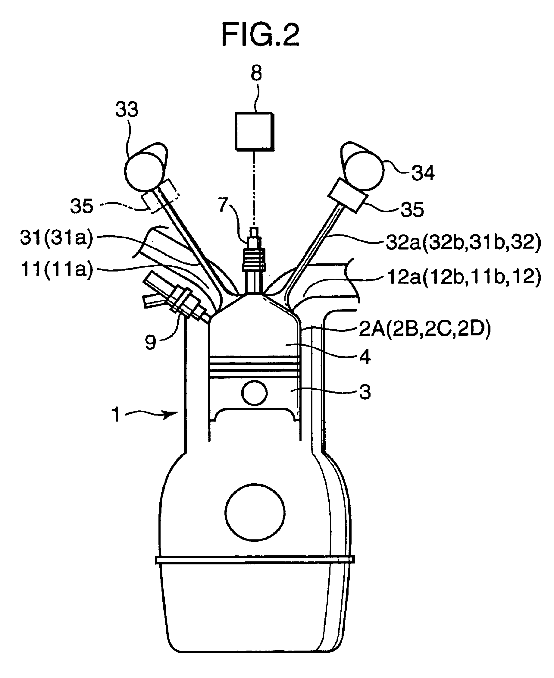
[0029]FIG. 1 is a diagram schematically showing the construction of a spark-ignition gasoline engine provided with a control device according to a preferred embodiment of the invention, and FIG. 2 is a diagram schematically showing the construction of one of cylinders of an engine body 1 together with such associated components as intake and exhaust valves provided in the cylinder.

[0030]Referring to these Figures, the engine body 1 has a plurality of cylinders. Specifically, the engine body 1 has four cylinders designated 2A, 2B, 2C and 2D in the illustrated embodiment. A piston 3 is fitted in each of these cylinders 2A-2D and a combustion chamber 4 is formed above the piston 3. There is installed a spark plug 7 at the top of the combustion chamber 4 in each cylinder 2 in such a way that a far end of the spark plug 7 is located inside the combustion chamber 4. The spark plug 7 is connected to an ignition circuit 8 which electronically controls ignition timing.

[0031]On one side of th...


PUM


Abstract

A control device switches an engine between normal operation mode and special operation mode. In the normal operation mode, an independent cylinder configuration is formed to produce combustion independently in individual cylinders. In the special operation mode, a two-cylinder interconnect configuration is formed so that burned gas discharged from preceding cylinders currently in an exhaust stroke is introduced into following cylinders currently in an intake stroke through intercylinder gas channels, a lean mixture having a high air-fuel ratio is combusted in the preceding cylinders, and a mixture produced by supplying fuel to the burned gas is combusted in the following cylinders. When the engine is switched between the special operation mode and the normal operation mode, the control device selects transitional operation mode, in which the two-cylinder interconnect configuration is formed, and interrupts combustion in the preceding cylinders while producing combustion in the following cylinders by compression ignition.

Description

BACKGROUND OF THE INVENTION[0001]1. Field of the Invention[0002]The present invention relates to a multicylinder spark-ignition engine of which individual cylinders undergo successive combustion cycles with specific phase delays.[0003]2. Description of the Related Art[0004]There exist conventionally known approaches to improving fuel economy of a spark-ignition engine. One approach to fuel economy improvement is to burn a mixture at an air-fuel ratio higher than the stoichiometric air-fuel ratio in individual cylinders of a spark-ignition engine. An example of this approach is disclosed in Japanese Unexamined Patent Publication No. 1998-29836. The approach of the Publication employs fuel injectors for injecting fuel directly into combustion chambers to produce stratified charge combustion by injecting the fuel during a compression stroke when the engine is in a low-load, low-speed range, for instance, so that the mixture is burned under extremely lean conditions.[0005]In this type o...

Claims


Application Information

Patent Timeline
Patent Type & Authority Patents(United States)
IPC IPC(8): F02B75/20F02B75/00F02F1/42F02M25/07F02B75/18F02F1/24F02D41/30F02D13/02F02D41/02
CPCF02B75/20F02D13/0276F02F1/4214F02M25/0746F02M25/0749F02M25/0752F02B2075/1816F02D41/0065F02D41/3064F02F2001/245Y02T10/18F02M26/01F02M26/40F02M26/43Y02T10/12
Inventor YAMAKAWA, MASAHISAARAKI, KEIJIHAYASHI, TAKAYOSHINISHIMOTO, TOSHIAKI
Owner MAZDA MOTOR CORP
Learn More