Erosion control reinforcement mat

a technology of erosion control and reinforcement mats, applied in soil conditioning compositions, excavations, applications, etc., can solve the problems of affecting soil fertility, unable to disclose the matting system, and posing potential installation problems and setbacks, so as to achieve effective resistance to high shear stress, withstand higher flow velocities, and increase mass unit density

Inactive Publication Date: 2005-08-16
GREENFIX AMERICA
View PDF15 Cites 37 Cited by
  • Summary
  • Abstract
  • Description
  • Claims
  • Application Information

AI Technical Summary

Benefits of technology

[0010]In one particularly useful embodiment of the invention, the system comprises a erosion control matting structured to substantially prevent soil loss on a substantially unvegetated, sloped surface, even when the matting is exposed to high velocity and/or long duration hydraulic events. (This embodiment of the invention may be hereinafter sometimes referred to as the high velocity/long duration hydraulic event matting embodiment.) More particularly, this embodiment of the invention generally comprises a core layer formed of a a fiber matrix comprising randomly oriented fibers, and a upper layer, bonded or secured to the core layer, wherein the core layer and the upper layer define a substantially flat upper surface. A flat upper surface is more specifically defined herein as a surface being without substantial three-dimensional features such as cuspations, pockets, ridges, or the like. Advantageously, the matting of this embodiment of the present invention has a substantially higher mass unit density in comparison to conventional erosion control mats. Specifically, the matting has a mass unit density of at least about 0.5 pounds per square yard and more preferably at least about 0.7 pounds per square yard. In this embodiment of the present invention, the fiber matrix core pre

Problems solved by technology

However, embankment and channel surfaces often require reinforcement, particularly during the pre-vegetated stage and early stages of plant growth, to prevent loss of soil, seeds, seedlings and other small plants when the soil is in an unstable state.
Although the Lancaster patent recognizes the problems associated with erosion on new channel surfaces, the matting system disclosed does not address other problems, for example, high shear stress on the matting, particularly during long duration, high velocity water flow during the critical pre-vegetated stage.
This requirement poses potential installation problems and setbacks.
For example, the

Method used


Image

  • Erosion control reinforcement mat
  • Erosion control reinforcement mat
  • Erosion control reinforcement mat

Examples


example

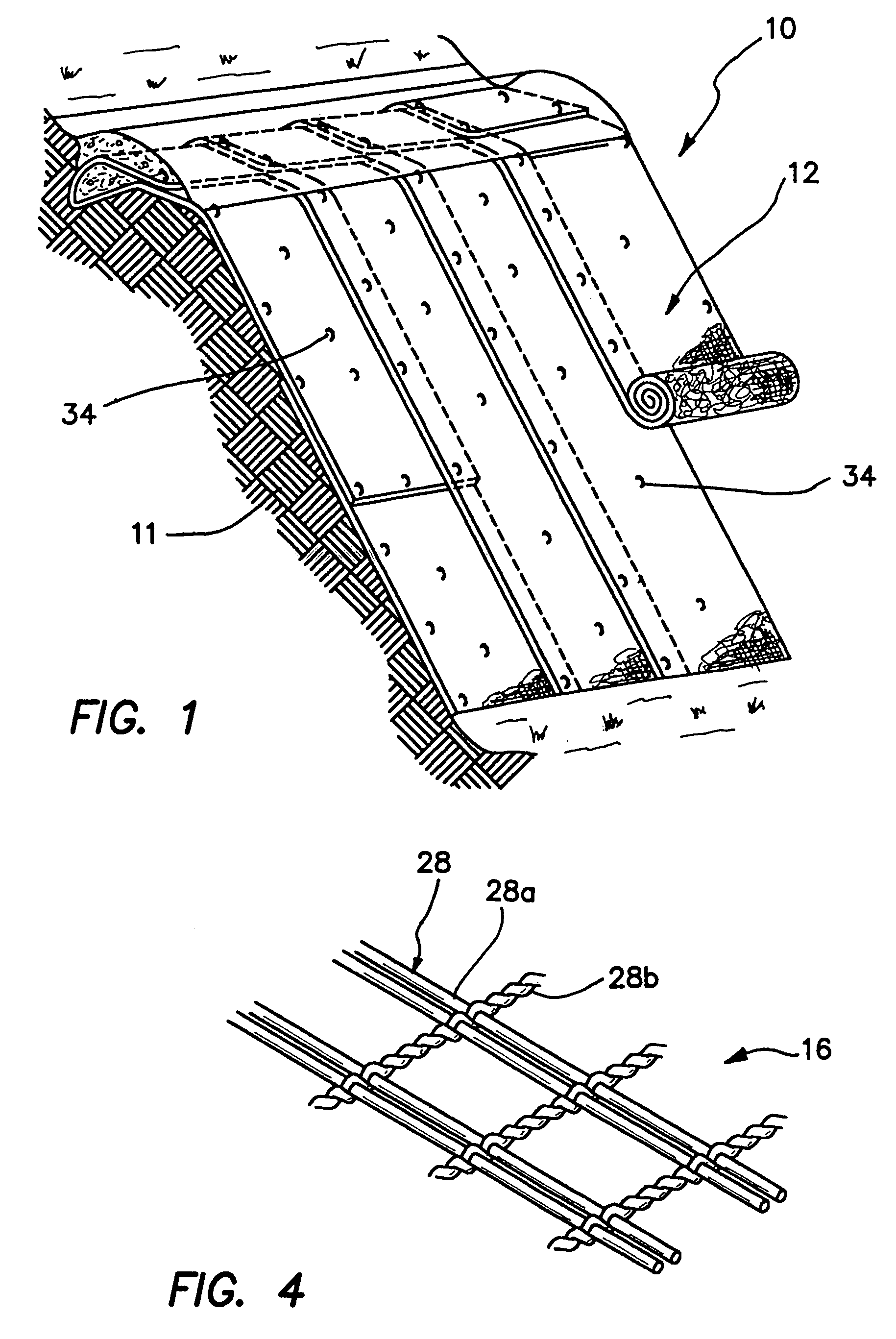
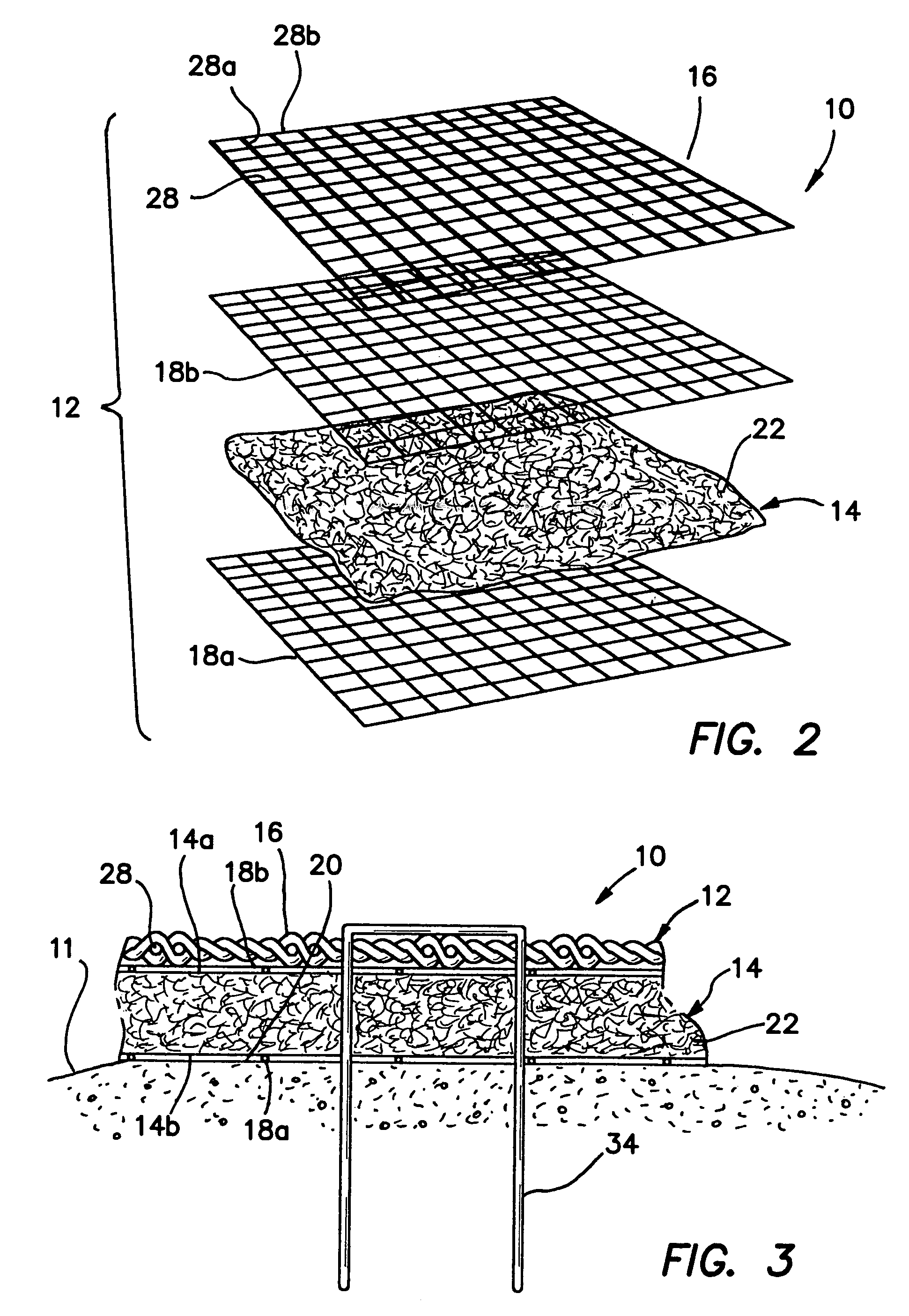
[0045]As a specific example, an erosion control system in accordance with the present invention comprises a fiber matrix core layer 14 of 100% coconut fiber and a permanent (non photodegradable) polypropylene biaxial geogrid upper surface 16. The matting is further reinforced with an upper net 18a and bottom net 18b and a monofilament thread having a strength of at least about 1000 denier. The matting 12 in accordance with this specific example has a weight of about 0.95 pounds per square yard, a thickness of at least about 0.32 inches. Despite the In addition, the matting has a tensile strength of up to about 172.6 pounds per square foot, and an elongation of up to about 18.1 percent and a Mannings “N” value of about 0.026. It is noted that these parameters (tensile strength, elongation) are significantly higher than conventional erosion control blankets having a similar flexibility. When said matting 12 is placed on or secured to a severely sloped, unvegetated channel surface, the...


PUM


Abstract

An erosion control system is provided which generally includes a flexible composite blanket or matting including a core layer bonded between an upper and a lower netting material, and an upper layer made of a biaxial geogrid. The matting has a flat upper surface without any substantial three dimensional features in which to trap sediment. The matting has a relatively high aerial density of about 0.7 pounds per square yard.

Description

RELATED APPLICATION[0001]This application claims the benefit of U.S. provisional application Ser. No. 60 / 266,782 filed on Feb. 6, 2001.BACKGROUND OF THE INVENTION[0002]The present invention generally relates to erosion control matting, and more specifically relates to temporary or permanent turf reinforcement and soil retention matting.[0003]Erosion control is an essential environmental consideration when new slope embankments and channels are created, for example during construction of buildings and drainage systems. Traditionally, newly constructed channels have been lined with concrete or rock to provide a hard, armor-like channel lining. Alternatively, the development of root reinforcement systems are relied upon to control erosion. Thus, methods have been developed for stabilizing soil on channel linings and other erosion prone surfaces by encouraging the growth of native or introduced vegetation along the surface. Ideally, a mature root system within the sloped surface functio...

Claims


Application Information

Patent Timeline
IPC IPC(8): C09K17/00C09K17/52
CPCC09K17/52
Inventor KIMBERLIN, MARK W.CHIRBAS, KURT
Owner GREENFIX AMERICA
Why Eureka
Try Eureka