Horizontal two stage rotary compressor

a compressor and horizontal technology, applied in the direction of machines/engines, liquid fuel engines, positive displacement liquid engines, etc., can solve the problems of affecting the volumetric reducing the efficiency of the compressor, and affecting the performance of the compressor, so as to reduce the number of compressor parts, simplify assembly, and reduce the load on the shaft

Inactive Publication Date: 2005-08-16
TECUMSEH PROD CO
View PDF27 Cites 32 Cited by
  • Summary
  • Abstract
  • Description
  • Claims
  • Application Information

AI Technical Summary

Benefits of technology

[0016]One advantage of the present invention is that the compression mechanisms being linked and driven by the rotor eliminates the need for a pair of precisely aligned and interconnected drive shafts to drive the compression mechanisms, thus reducing the load on the shaft.
[0017]A further advantage of the present invention is that the compressor may be mounted to either a substantially horizontal or vertical grounding surface without requiring a different mounting assembly.
[0018]An additional advantage of the present invention is that the eccentrics are integrally formed with the stationary shaft, thereby reducing the number of compressor parts and simplifying assembly.

Problems solved by technology

When the compression mechanisms are located adjacent one another, on one side of the motor, problems may occur during compressor operation.
Such problems may include overheating of the suction gas supplied to the first stage compression mechanism which affects volumetric efficiency of the compressor performance.
Further, overheating due to the closeness of the compression mechanisms may create problems including additional reduction of the compressor efficiency and possible reliability issues.
If the suction or cooled intermediate pressure gas is overheated as discussed above, the motor and the gas entering the second stage compression mechanism may not be sufficiently cooled.
If, for example, alternative refrigerants are used and the compression mechanisms are in a parallel configuration, the compression mechanisms may be unable to withstand the high operating pressure experienced during compression of some refrigerants such as carbon dioxide.
The slightest misalignment of the drive shafts will result in dynamic instability.
Misalignment of the shafts may also increase the load on the eccentrics, outboard bearings, and main bearings of the compression mechanisms, which in turn will trigger excessive vibration and noise during compressor operation.
The excess loads may cause premature failure of the bearings.
By providing the compressor with an eccentric that is an independent component from the drive shaft, assembly of the compressor may be complicated.
Further, vibration and thus noise may be produced from the eccentric and drive shaft assembly if, for example, the eccentric becomes loose on the shaft.

Method used


Image

  • Horizontal two stage rotary compressor
  • Horizontal two stage rotary compressor
  • Horizontal two stage rotary compressor

Examples


Embodiment Construction

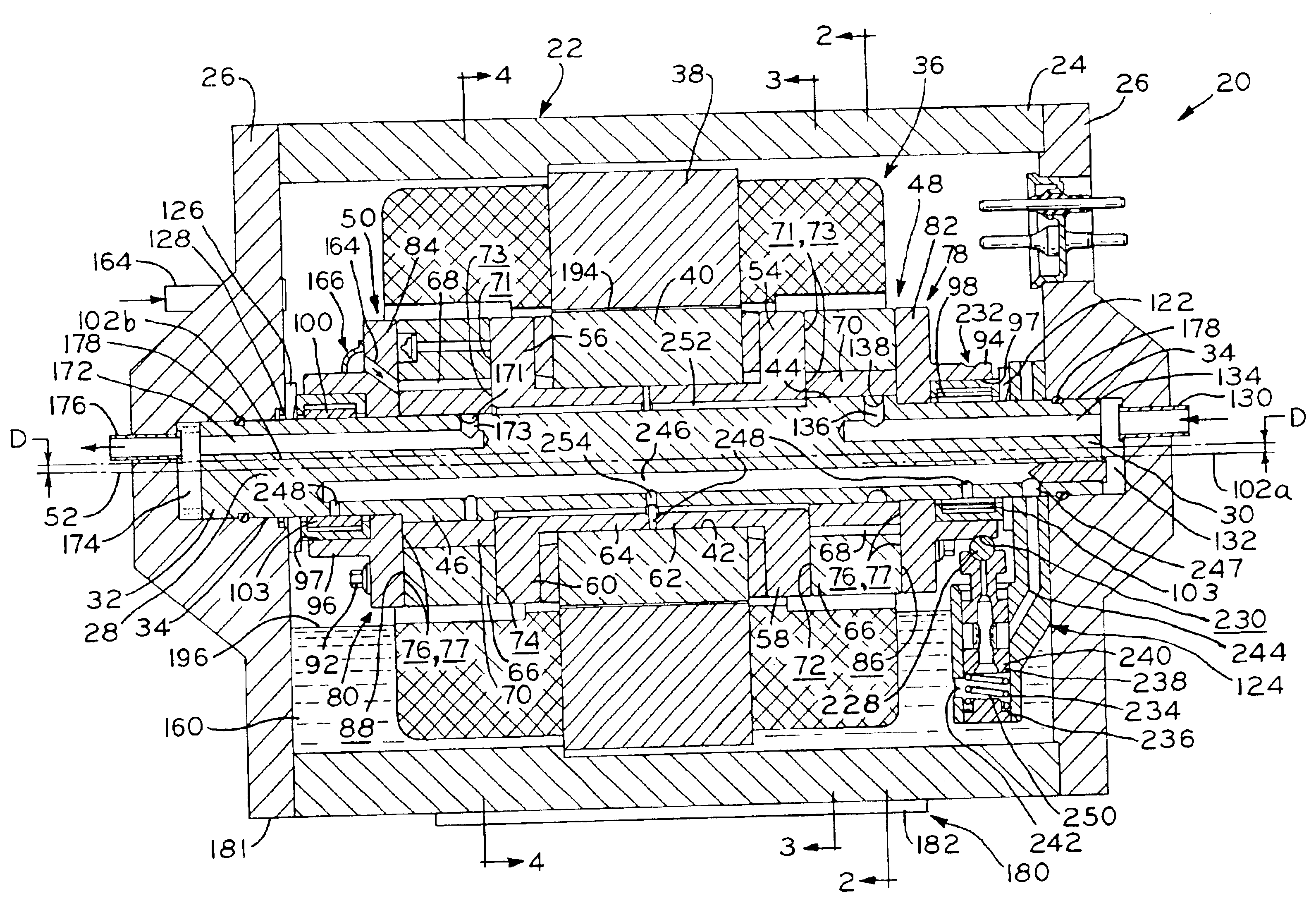
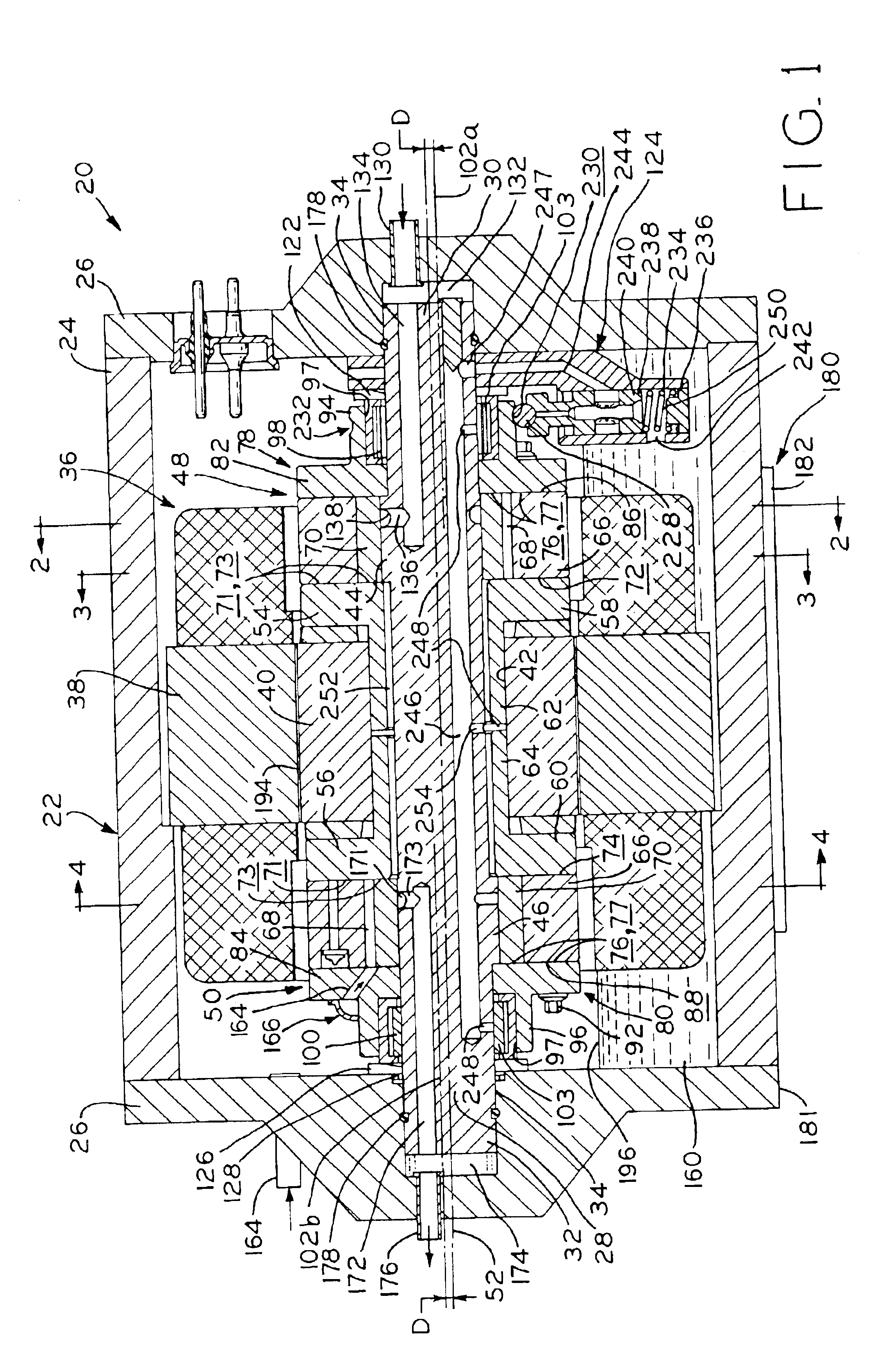
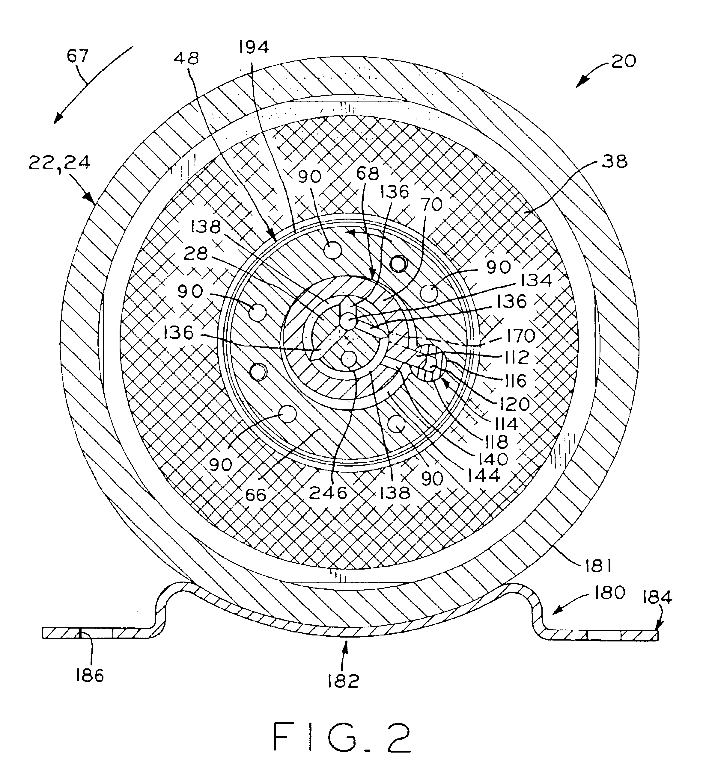
[0040]Referring to FIG. 1, two-cylinder, two stage rotary horizontal compressor 20 for use in a refrigeration system. Compressor 20 includes hermetically sealed housing 22 defined by main body portion 24 having end caps 26 mounted to each end thereof by any suitable method including welding, brazing, or the like. Mounted within compressor housing 22 is non-rotating, stationary shaft 28 having opposite ends 30 and 32 mounted in recesses 34 formed in each end cap 26. Located in main body portion 24 of compressor housing 22 is electric compressor motor 36 including stator 38 and rotor 40. Stator 38 is, e.g., interference or shrink fitted in main body portion 24 to mount motor 36 therein and is rigidly mounted in surrounding relationship of rotor 40. Rotor 40 is provided with central aperture 42 extending the length thereof in which shaft 28 is received such that rotor 40 is rotatably disposed about the stationary shaft.

[0041]Eccentrics 44 and 46 are integrally formed near opposite shaf...


PUM


Abstract

A hermetic two stage rotary compressor having a housing with a stationary shaft fixedly mounted in the housing. A motor having a rotor and a stator is mounted in the housing with the rotor being rotatably mounted on the shaft. A pair of compression mechanisms are rotatably mounted on the shaft with one compression mechanism being located adjacent a first end of the rotor, and one compression mechanism being located adjacent a second end of the rotor. The compression mechanisms are operatively associated with the rotor such that rotation of the rotor drives the compression mechanisms. A fluid flow path is defined in the compressor including a plurality of longitudinal bores formed in the stationary shaft. A mounting assembly is attached to the housing so as to mount the compressor in either a substantially horizontal or vertical orientation. The pump is positioned so as to be at least partially immersed in an oil sump in the housing when the compressor in either orientation.

Description

BACKGROUND OF THE INVENTION[0001]The present invention relates to hermetic compressors and more particularly to two stage rotary compressors using carbon dioxide as the working fluid.[0002]Conventionally, multi-stage compressors are ones in which the compression of the refrigerant fluid from a low, suction pressure to a high, discharge pressure is accomplished in more than one compression process. The types of refrigerant generally used in refrigeration and air conditioning equipment include chlorofluorocarbons (CFCs) and hydrochlorofluorocarbons (HCFCs). Additionally, carbon dioxide may be used as the working fluid in refrigeration and air conditioning systems. By using carbon dioxide refrigerant, ozone depletion and global warming are nearly eliminated. Carbon dioxide is non-toxic, non-flammable, and has better heat transfer properties than CFCs and HCFCs, for example. The cost of carbon dioxide is significantly less than CFC and HCFC. Additionally, it is not necessary to recover ...

Claims


Application Information

Patent Timeline
Patent Type & Authority Patents(United States)
IPC IPC(8): F04C18/30F04C18/328F04B39/02F04C23/00F04C29/02F04C18/32F04C18/356
CPCF04B39/0261F04C18/322F04C18/328F04C23/008F04C29/025Y10S417/902
Inventor DREIMAN, NELIK I.BUNCH, RICK L.
Owner TECUMSEH PROD CO
Why Eureka
Try Eureka