
Polishing apparatus

a technology of polishing apparatus and cleaning cloth, which is applied in the direction of polishing machines, manufacturing tools, transportation and packaging, etc., can solve the problems of increasing the operating cost of the polishing apparatus, and achieve the effect of increasing the level of cleanliness and preventing contamination

Inactive Publication Date: 2005-08-16
EBARA CORP
View PDF29 Cites 4 Cited by
  • Summary
  • Abstract
  • Description
  • Claims
  • Application Information

AI Technical Summary

Benefits of technology

[0007]The present invention has been made in view of the above problems. It is a first object of the present invention to provide a polishing apparatus having an independent chamber defined by a partition with a shutter and disposed between a processing section including a polishing section, a cleaning section and the like and a receiving section including wafer cassette units, the independent chamber having an increased level of cleanliness for preventing contamination from being introduced from the processing section into the receiving section.
[0010]In the first aspect of the present invention, contaminants in the processing section are prevented from reaching the receiving section such as a wafer cassette unit, and hence cleanliness of the processing section is not required to be enhanced to an unnecessarily high level, and the receiving section may be kept clean.

Problems solved by technology

As a result, the cleanliness of the processing section is required to be higher than necessary, thus increasing the operating cost of the polishing apparatus, and the cleanliness of the semiconductor wafers in the wafer cassettes depends on the cleanliness of the processing section.

Method used


Image

  • Polishing apparatus
  • Polishing apparatus
  • Polishing apparatus

Examples


Embodiment Construction

[0024]A polishing apparatus according to an embodiment of the present invention will be described below with reference to the drawings.

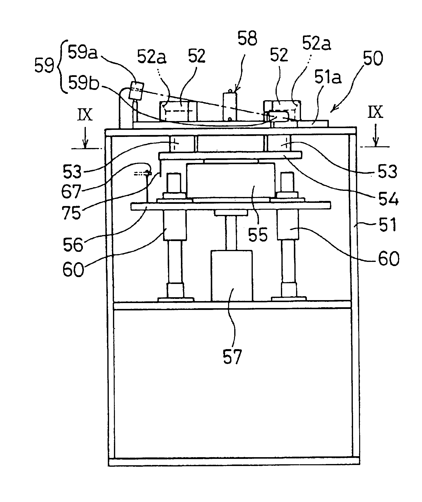
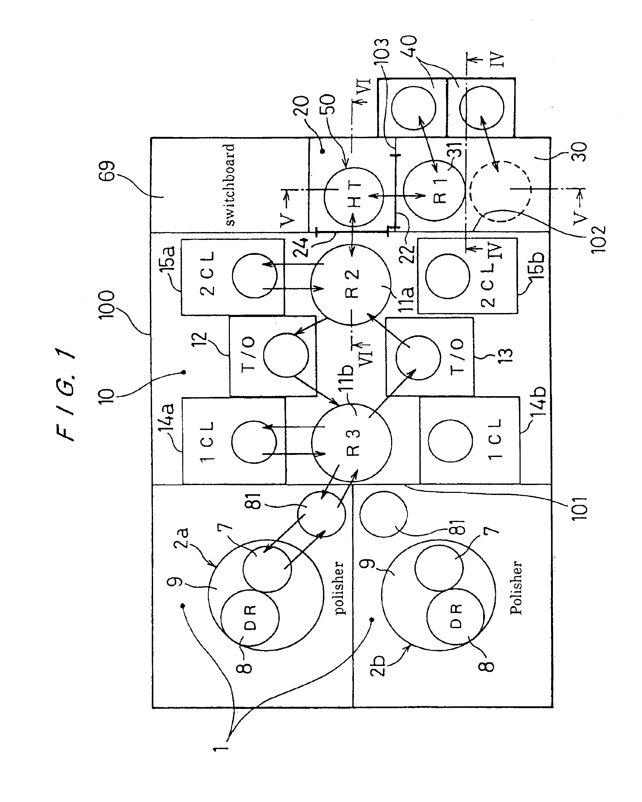
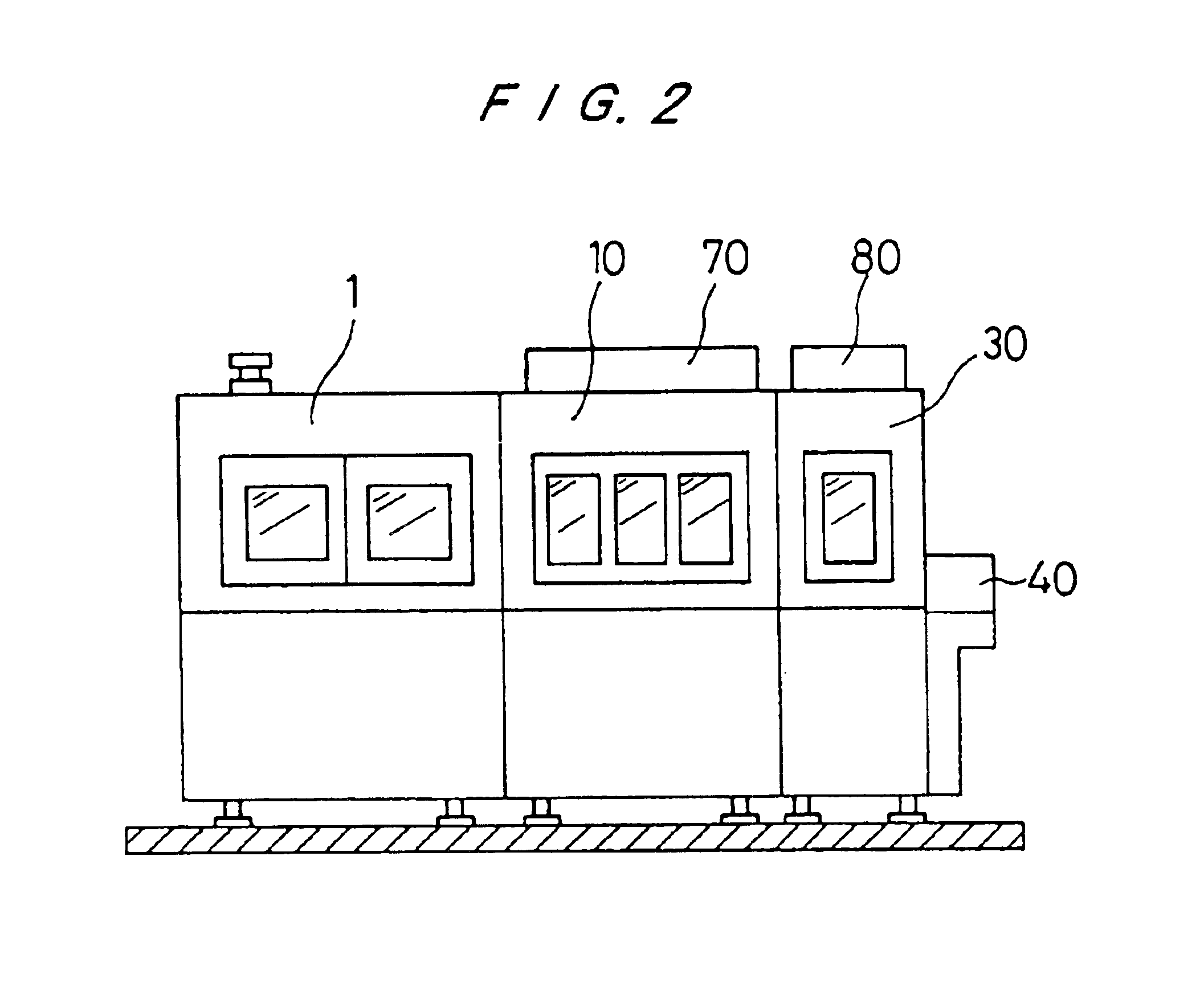
[0025]FIG. 1 is a plan view of a polishing apparatus according to the present invention, and FIG. 2 is a side elevational view showing an appearance of the polishing apparatus. As shown in FIGS. 1 and 2, the polishing apparatus comprises a polishing section 1, a cleaning section 10, a clean chamber 20, a load and unload section 30, and wafer cassette units 40. All the components of the polishing apparatus, except for the wafer cassette units 40, are accommodated in a housing 100.

[0026]In the polishing section 1, a pair of polishing units 2a, 2b are disposed in laterally confronting relation to each other. In the cleaning section 10, two SCARA robots 11a, 11b are dispersed in a central region thereof, a pair of reversing machines 12, 13 are disposed one on each side of the SCARA robots 11a, 11b, and two primary cleaning machines 14a, 14b and two secon...


PUM


Abstract

The present invention relates to a polishing apparatus for polishing a workpiece such as a semiconductor wafer. The polishing apparatus has a processing section including a polishing section (1) for polishing a semiconductor wafer (6) and a cleaning section (10) for cleaning a polished semiconductor wafer, a receiving section (40) for supplying a semiconductor wafer (6) to be polished to the processing section and receiving a polished semiconductor wafer (6), and a cleaning chamber (20) disposed between the processing section and the receiving section and defined by partitions (102, 103) with shutters (22, 24) which separate the processing section and the receiving section from each other.

Description

[0001]This is a divisional application of Ser. No. 09 / 423,445, filed Nov. 9, 1999 now U.S. Pat. No. 6,293,855.TECHNICAL FIELD[0002]The present invention relates to a polishing apparatus, and more particularly to a polishing apparatus for polishing a workpiece such as a semiconductor wafer to a flat mirror finish.BACKGROUND ART[0003]Recent rapid progress in semiconductor device integration demands smaller and smaller wiring patterns or interconnections and also narrower spaces between interconnections which connect active areas. If a photolithographic process is used to form circuits, then since the depth of focus of the optical system is relatively small, the focused surface of a stepper requires a high level of flatness One of the available processes for planarizing surfaces of semiconductor wafers is a chemical mechanical polishing (CMP) conducted by a polishing apparatus in which while supplying an abrasive liquid containing abrasive particles to a polishing cloth mounted on a ro...

Claims


Application Information

Patent Timeline
IPC IPC(8): B24B37/04H01L21/00B24B37/10B24B37/27H01L21/304H01L21/677
CPCB24B37/04B24B37/345H01L21/67161H01L21/67219H01L21/67259H01L21/67745H01L21/681B23Q15/24B24B37/10B24B37/30H01L21/30625
Inventor YOSHIDA, MASAOSEKIMOTO, MASAHIKO
Owner EBARA CORP
Learn More