Optical device including dynamic channel equalization

a technology of optical channel and dynamic equalization, which is applied in the field of optical devices including dynamic equalization of optical channel bands, can solve the problems of limited tdm capacity, prohibitive expansion cost, and limited current capacity of existing waveguide media

Inactive Publication Date: 2005-08-16
CIENA
View PDF17 Cites 16 Cited by
  • Summary
  • Abstract
  • Description
  • Claims
  • Application Information

AI Technical Summary

Benefits of technology

[0014]In a demultiplexer configuration, a device consistent with the invention may include an optical communication path receiving an optical signal including a plurality of separate wavelengths. The optical performance monitor may be coupled to the optical communication path. An optical separator receives an output of the optical performance monitor, and supplies each of the plurality of groups of the separate wavelengths on a separate associated output. Each of a plurality of variable optical attenuators receives a separate one of the separate associated outputs for adjusting an associated attenuation level.

Problems solved by technology

While this is a useful technique for carrying plural information sources on a single channel, TDM capacity is limited by fiber dispersion and the need to generate high peak power pulses.
While the need for communication services increases, the current capacity of existing waveguiding media is limited.
Although capacity may be expanded e.g., by laying more fiber optic cables, the cost of such expansion is prohibitive.
In high channel count systems, however, it is difficult to multiplex and demultiplex a large number of optical channels.
For example, in a 40 channel DWDM system, a 1×40 splitter would be inadequate to demultiplex each of the channels because the power level at each output of such a splitter would be insufficient to maintain an adequate signal to noise ratio.
As a result, the transmitted channels cannot be adequately detected.
On the other hand, although an optical amplifier could be used to increase the power on the input of the 1×40 splitter, such an amplifier can be difficult to manufacture, and would fail to provide the requisite optical power per channel at higher channel counts.
Moreover, if amplifiers were to be provided at each of the outputs of the 1×40 splitter, the cost of the demultiplexer would be excessive.
In addition, signal detection in high channel count, high data rate, and long distance systems can be unreliable as a result of varying signal optical power levels resulting from conventional multiplexing and demultiplexing operations.
For example, wavelength dependent variations in the gain or transmission characteristics of network elements can result in significant variations in the optical signal power and signal to noise ratio in the transmitted channels.
Thus the difficulties associated with output signal power variations in the transmitted channels persist.

Method used


Image

  • Optical device including dynamic channel equalization
  • Optical device including dynamic channel equalization
  • Optical device including dynamic channel equalization

Examples


Embodiment Construction

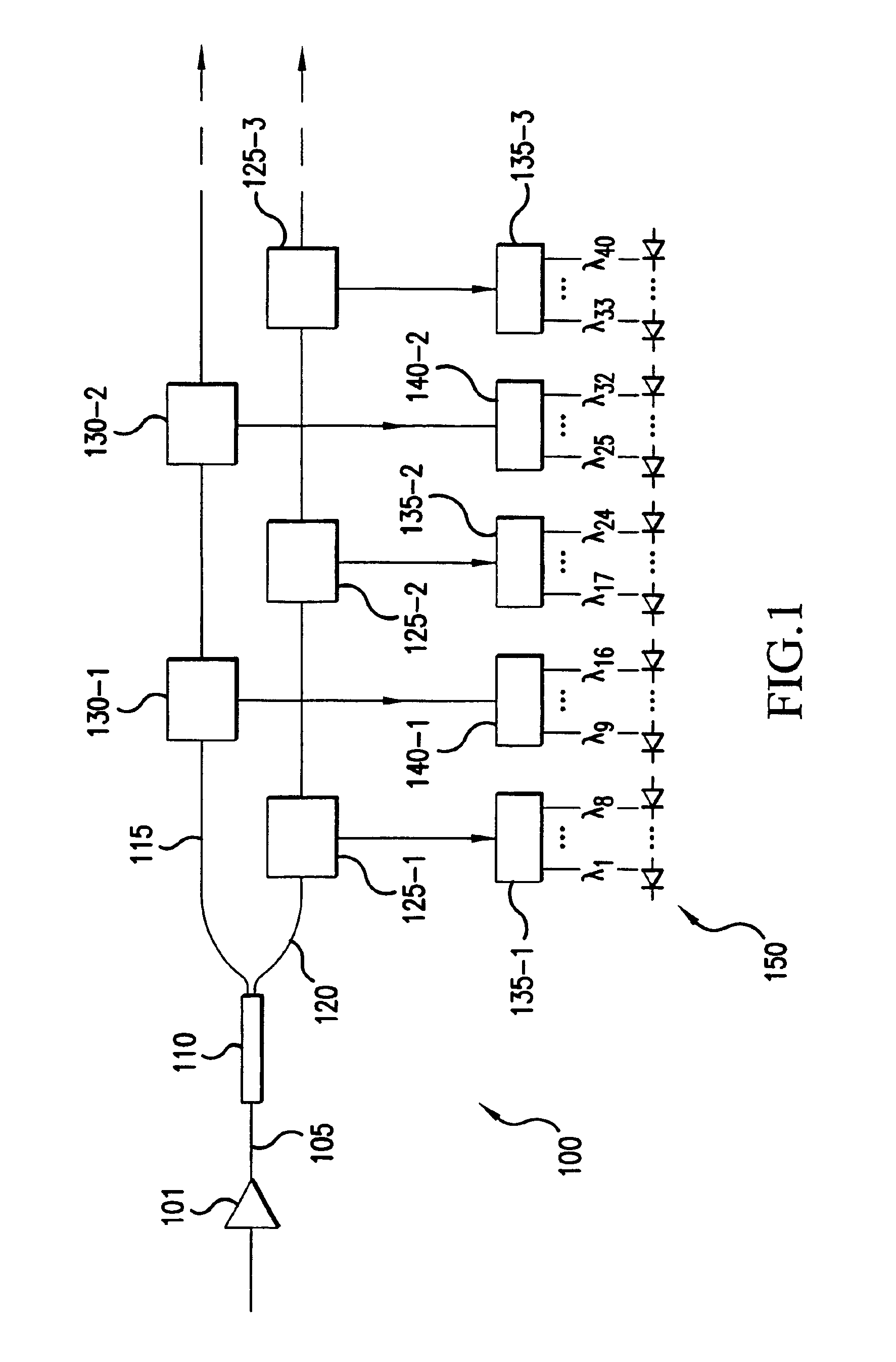
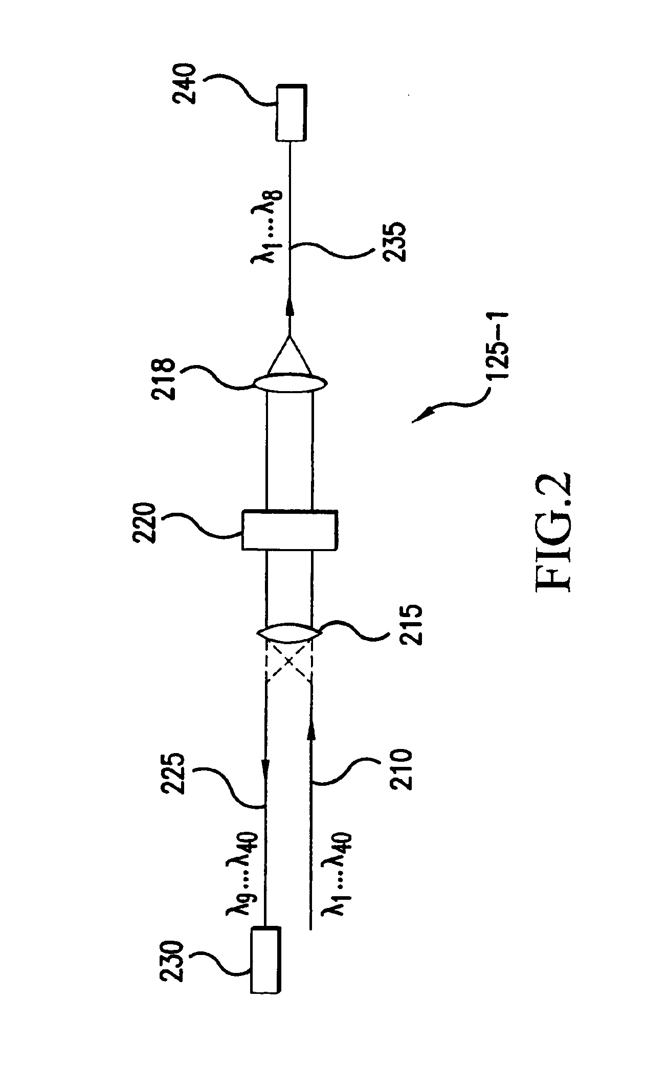
[0037]In accordance with the present invention, optical channels to be demultiplexed are supplied to first and second optical fibers via an optical splitter. Low loss interference filters, for example, coupled to the first and second optical fibers, select respective groups of channels. Each group of channels is next demultiplexed with sub-demultiplexers into individual channels, each of which is then sensed with a corresponding photodetector. Although the optical splitter introduces an optical power loss at the input to the demultiplexer, the interference filters and sub-demultiplexers create little additional loss. As a result, the total power loss associated with the present invention is significantly less than that obtained with a conventional n channel demultiplexer based on a 1×n splitter. Accordingly, large numbers of channels, e.g., in excess of forty can be readily demultiplexed and detected.

[0038]Turning to the drawings in which like reference characters indicate the same ...


PUM


Abstract

An optical device including dynamic channel equalization is provided. In an exemplary multiplexer or line amplifier configuration the device includes a plurality of separate optical paths, each of which receiving a separate group of optical signals. Each group of optical signals is provided to an associated variable optical attenuator. Separate inputs of an optical combiner are each coupled to an output of an associated one of the variable optical attenuators. The optical combiner has an output providing the separate groups of optical signals in an aggregated form on an aggregate optical signal path. An optical performance monitor is coupled to the aggregate optical signal path, and is configured to detect an optical signal to noise ratio of each of the separate groups. The monitor supplied a feedback signal to corresponding ones of the variable optical attenuators for adjusting a respective attenuation associated with each of the attenuators in dependence of the detected optical signal to noise ratios. The device may also be provided in a demultiplexer configuration.

Description

[0001]This application is a Divisional of application Ser. No. 09 / 493,313, filed on Jan. 28, 2000 now U.S. Pat. No. 6,760,532, and for which priority is claimed under 35 U.S.C. § 120 the entire contents of all are hereby incorporated by reference.FIELD OF THE INVENTION[0002]The present invention is directed in general to optical devices, and, more particularly, to an optical device including dynamic equalization of optical channel bands for achieving improved performance in a wavelength division multiplexed system.[0003]Optical communication systems are a substantial and fast growing constituent of communication networks. The expression “optical communication system,” as used herein, relates to any system that uses optical signals to convey information across an optical waveguiding medium, for example, an optical fiber. Such optical systems include but are not limited to telecommunication systems, cable television systems, and local area networks (LANs). Currently, the many optical ...

Claims


Application Information

Patent Timeline
Patent Type & Authority Patents(United States)
IPC IPC(8): H04B10/17H04B10/08H04L25/03
CPCH04B10/077H04B10/07955H04B10/296H04L2025/03477H04L2025/03611
Inventor LIVAS, JEFFREY C.BRENNER, TOMAS
Owner CIENA
Why Eureka
Try Eureka