

Freeze-drying apparatus
- Summary
- Abstract
- Description
- Claims
- Application Information
AI Technical Summary
Benefits of technology
Problems solved by technology
Method used
Image

Examples
examples
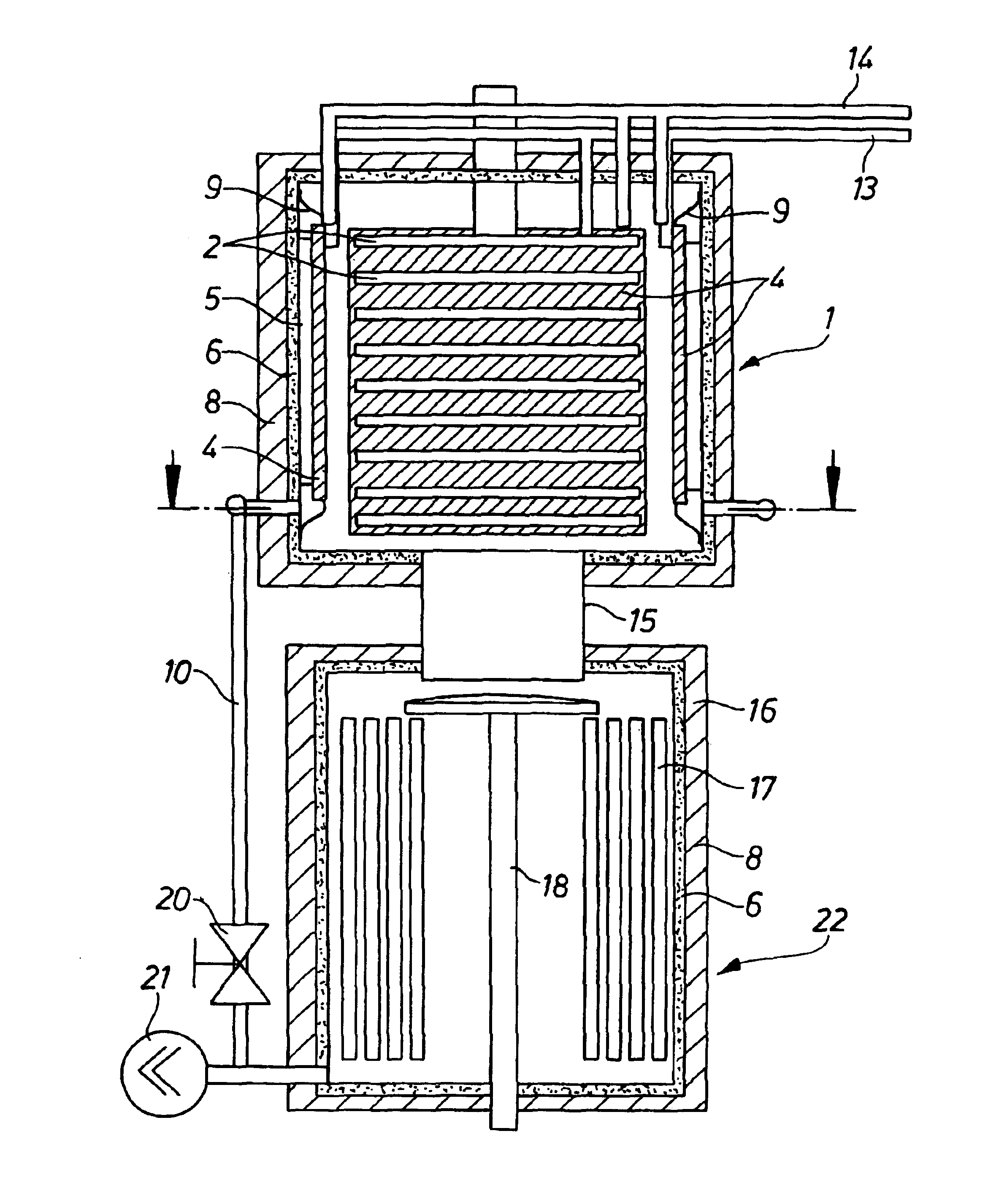
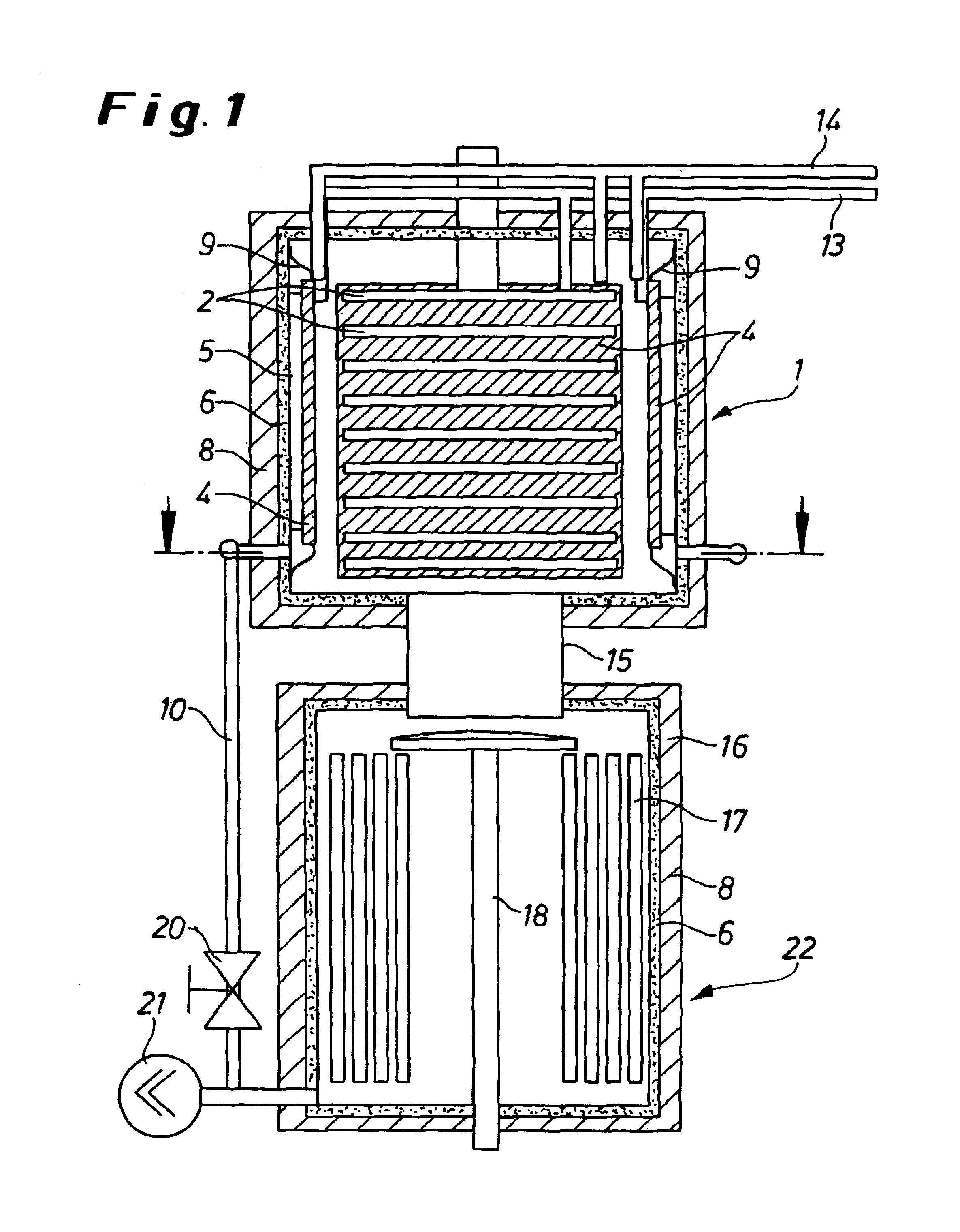
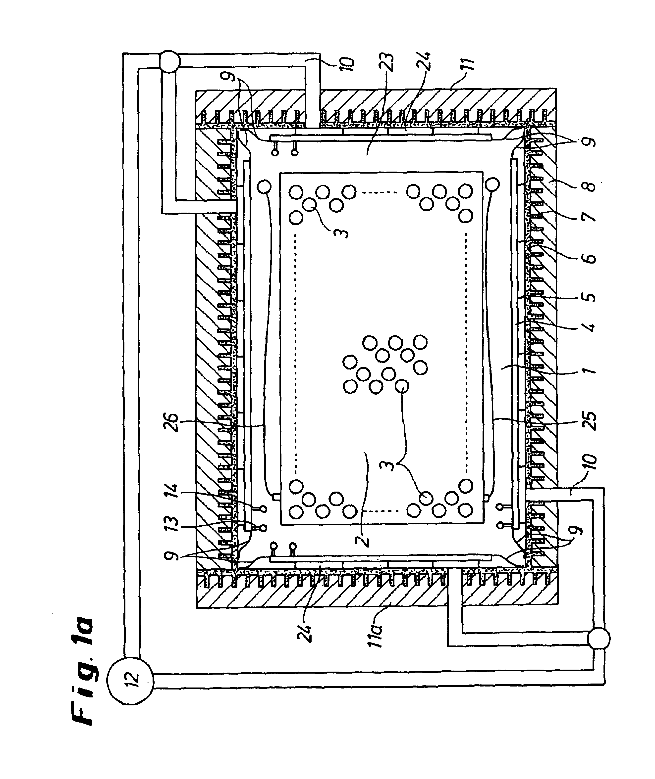
[0056]FIG. 1 shows a system comprising freeze-drying chamber 1 and condenser chamber 22, in which drums of product-filled vessels are frozen and freeze-dried. FIG. 1a shows vessels 3 standing on the stand plate 2 in the edge region and in the central region. The chamber 1 has two doors 11, 11a which are sealed and can be opened separately. The freeze-drying chamber 1 has a two-shell structure. The heavy chamber-wall structure 6 with reinforcing ribs 7 has the task of providing a vacuum-tight, tortionally rigid housing, which is able to withstand the atmospheric pressure when the freeze-drying chamber 1 is evacuated, for the second, inner chamber 23 which is integrated therein. The chamber 1 is provided with thermally insulating material 8 on its outer side, to prevent heat exchange with the environment. The inner freeze-drying chamber 23 is formed from the heating / cooling plates 4, which are held at a distance from the chamber wall 6 with the aid of spacers 5 and are connected to th...
example 2
[0059]FIG. 2 shows an embodiment of the freeze-dryer which differs in terms of the way in which the heating / cooling plates 4′ are arranged. In this case, the temperature-controlled plates 4′ are suspended freely in the chamber 23. The heating / cooling plates 4′ are suspended parallel to and at a distance from the edges of the standing plates 2, so that space is retained for all the equipment associated with the stand plates 2, for example hoses 25, 26 for the heat-transfer medium, stand-plate holders (not shown).
[0060]Known CIP / SIP features (automatic cleaning and sterilization systems) may additionally be provided in the interior of the chamber. The heating / cooling plates 4′ are in turn fed with the heat-transfer medium from a separate heat-transfer circuit via inlet 13 and return 14. The mass of the heating / cooling plates in both embodiments (in accordance with Examples 1 and 2) corresponds to the mass of the stand plates 2, so that the heating / cooling dynamics of the plates 2 and ...
PUM
 Abstract
Description
Claims
Application Information