Internal combustion engine ignition apparatus

a technology of ignition apparatus and internal combustion engine, which is applied in mechanical equipment, machines/engines, electric control, etc., can solve the problems of insufficient ignition energy to the engine, degrading the ignition characteristic of the variation in the level of the ignition signal voltage, and complicated terminal structure, so as to avoid the degradation of the ignition characteristic by the variation in the ignition signal voltage level, simplify the terminal structure, and maintain the operation level of the switching circuit constant

Active Publication Date: 2005-08-23
MITSUBISHI ELECTRIC CORP
View PDF9 Cites 4 Cited by
  • Summary
  • Abstract
  • Description
  • Claims
  • Application Information

AI Technical Summary

Benefits of technology

[0009]The present invention provides an internal combustion engine ignition apparatus which is improved, in a switching circuit having no power supply terminal connected to a battery and having an output terminal, an input terminal and a reference potential terminal, so that an ignition characteristic is not degraded by a level variation in ignition signal voltage.
[0012]In the internal combustion engine ignition apparatus of the invention, the switching circuit does not have the power supply terminal connected to the battery, but has the three terminals of the output terminal, the input terminal and the reference potential terminal, and the terminal structure can be simplified. In addition, the current supply circuit includes the constant current circuit, and this constant current circuit supplies the driving current, which is made the constant current, to the drive resistor, so that the driving current in the on state of the switching circuit is made the constant current, and even if the level of the ignition signal voltage varies, the operation level of the switching circuit can be kept constant, and the degradation of the ignition characteristic by the variation in the ignition signal voltage level can be avoided.

Problems solved by technology

However, since the four terminals including the power supply terminal is included, the terminal structure becomes complicated.
However, in the internal combustion engine ignition apparatus of this type which has no power supply terminal connected to a battery, since the switching element connected to the primary coil of the ignition coil is driven by the ignition signal voltage supplied to the input terminal, there is a disadvantage that variation in the level of the ignition signal voltage degrades the ignition characteristic.
For example, in an on state of the switching element, although a current increasing with the lapse of time flows through the primary coil of the ignition coil by the influence of its inductance, when the level of the ignition signal voltage is low in the on state of the switching element, energization to the primary coil of the ignition coil is performed in the state where the on resistance of the switching element is relatively large, so that the switching element is turned off in the state where the current of the primary coil of the ignition coil is not increased to a sufficient value, and there occurs a case where a sufficient ignition voltage can not be generated, ignition energy to the engine is insufficient, and engine output is lowered or misfire occurs in which ignition for the engine is not performed.
Besides, in the on state of the switching element, when the ignition signal voltage pulsates by noise, the flowing current of the primary coil of the ignition coil is also varied, and there is a fear that erroneous ignition occurs at an erroneous timing which is not the ignition timing, and by the pulsation of the ignition signal voltage, even if the erroneous ignition does not occur, the switching element is turned off in the state where the current of the primary coil of the ignition coil is not increased up to a sufficient value, so that a sufficient ignition voltage is not generated, the ignition energy for the engine is insufficient, and the engine output is lowered.

Method used


Image

  • Internal combustion engine ignition apparatus
  • Internal combustion engine ignition apparatus
  • Internal combustion engine ignition apparatus

Examples


embodiment 1

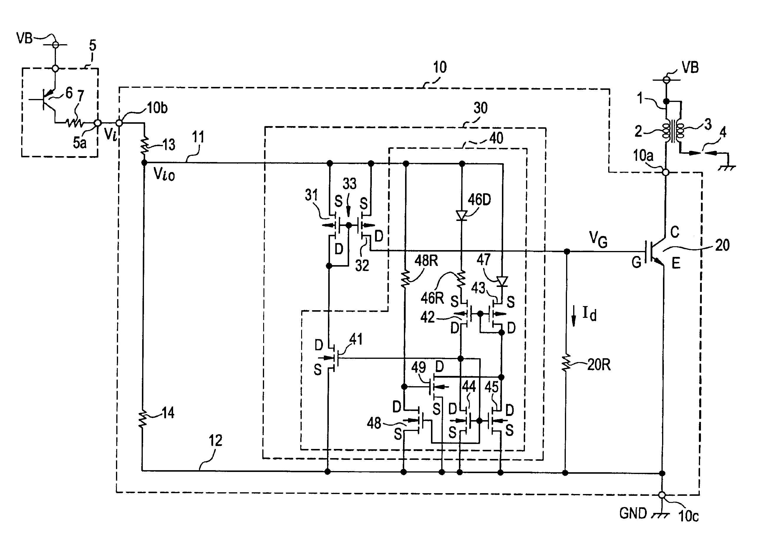
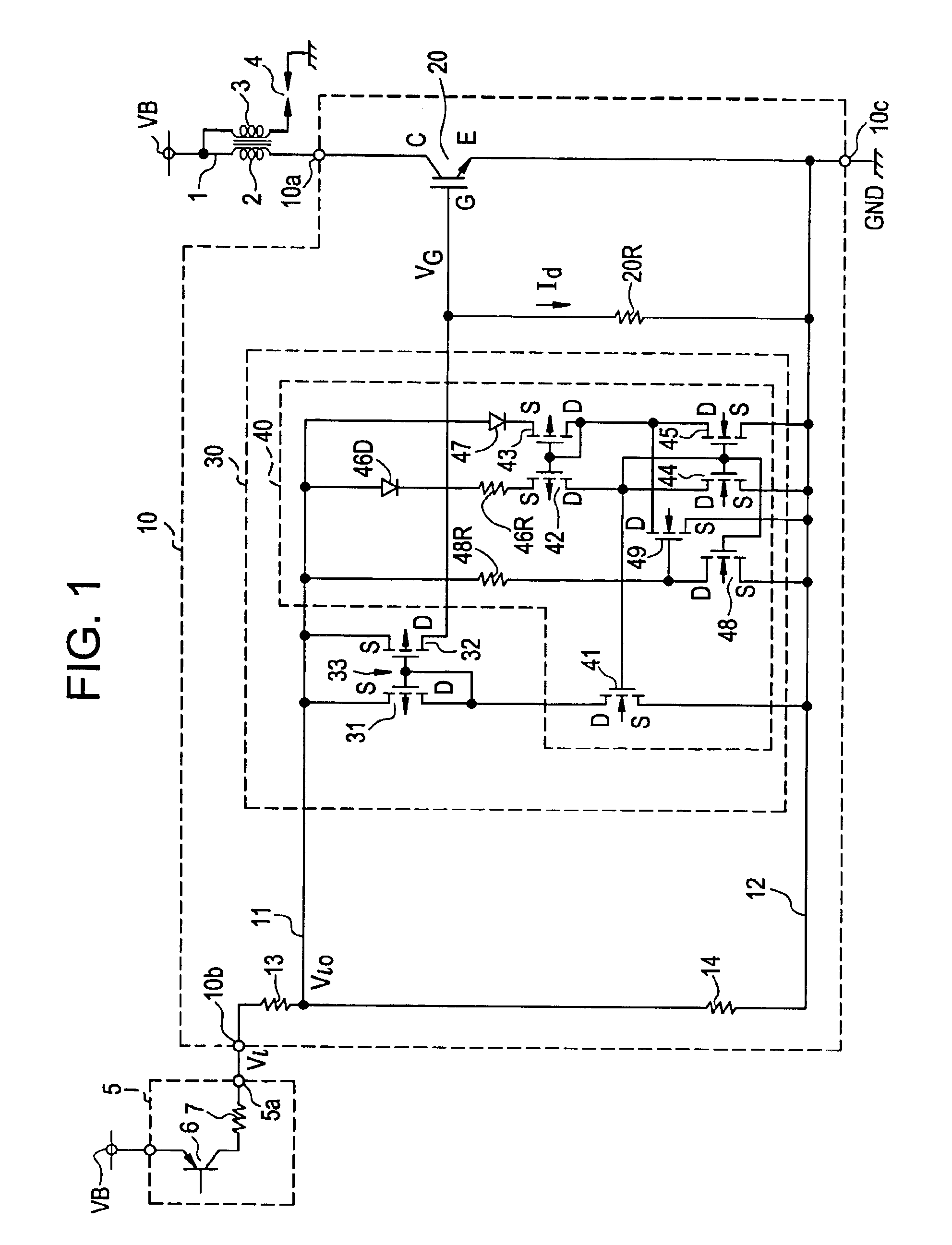
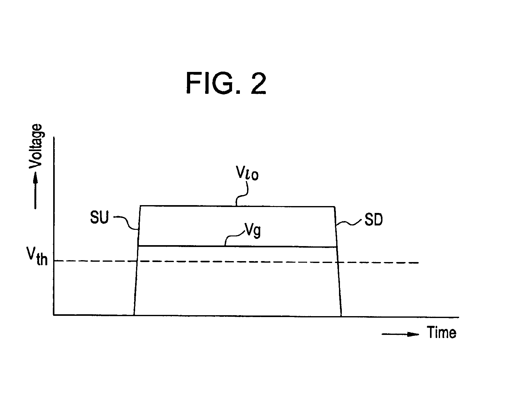
[0025]FIG. 1 shows embodiment 1 of an internal combustion engine ignition apparatus of the invention. FIG. 2 is a characteristic diagram for explaining the operation of the embodiment 1.

[0026]The internal combustion engine ignition apparatus of the embodiment 1 is an ignition apparatus for an internal combustion engine mounted in an automobile, and includes an ignition coil 1, an ignition driving circuit 5, and a switching circuit 10. The ignition coil 1 includes a primary coil 2 and a secondary coil 3, and is connected to a power supply terminal VB such as an on-board battery. The on-board battery has, for example, 12 volts, and the power supply terminal VB has, for example, 12 volts. A spark plug 4 is connected to the secondary coil 3. This spark plug 4 is disposed in a combustion chamber of the internal combustion engine, and ignites fuel, such as gasoline, supplied into the combustion chamber to burn it.

[0027]The ignition driving circuit 5 is included in an electrical control un...

embodiment 2

[0047]FIG. 3 shows embodiment 2 of an internal combustion engine ignition apparatus of the invention. This embodiment 2 uses a switching circuit 10B. The switching circuit 10B is such that a current limiting circuit 60 is added to the switching circuit 10 of the embodiment 1 shown in FIG. 1, and along with this, instead of the switching element 20 shown in FIG. 1, a switching element 20A having an auxiliary emitter E1 is used. Since the others are constructed similarly to the embodiment 1, the same parts are denoted by the same symbols, and the explanation will be omitted.

[0048]The switching element 20A is an IGBT, and this includes a collector C, a main emitter E, an auxiliary emitter E1, and a gate G. The collector C is directly connected to an output terminal 10a of a switching circuit 10B, and the main emitter E is directly connected to a reference potential terminal 10b.

[0049]The current limiting circuit 60 is a protection circuit serving to limit a flowing current of the swit...

embodiment 3

[0061]FIG. 6 is an electrical diagram showing embodiment 3 of an internal combustion engine ignition apparatus of the invention. In the embodiment 3, a switching element 20B obtained by modifying the switching element 20A of FIG. 3 is used, and a current limiting circuit 60A obtained by modifying the current limiting circuit 60 of FIG. 3 is used. Similarly to the embodiment 2 shown in FIG. 3, this embodiment has a function to protect the switching element. In this embodiment 3, since the others other than the switching element 20B and the current limiting circuit 60A are the same as the embodiment 2 shown in FIG. 3, the same parts are denoted by the same symbols and the explanation will be omitted.

[0062]The switching element 20B used in the embodiment 3 is an IGBT, and incorporates a main IGBT 21, a sense IGBT 24 and a latch-up element 27. The main IGBT is such that an N-channel MOS transistor 22 and a PNP bipolar transistor 23 are connected in series to each other. A drain D of the...


PUM


Abstract

There is proposed an internal combustion engine ignition apparatus in which a switching circuit having no power supply terminal connected to a power supply such as a battery, and includes an output terminal connected to an ignition coil, an input terminal for receiving supply of an ignition signal voltage, and a reference potential terminal connected to a reference potential. A current supply circuit is connected between the input terminal and the reference potential terminal, and a current is supplied from the current supply circuit to a drive resistor of the switching element. This current supply circuit is controlled by a constant current circuit, and supplies a driving current, which is made a constant current, to the drive resistor between a rising portion of the ignition signal voltage and a falling portion thereof. The driving current, which is made the constant current, keeps the gate voltage of the switching element being constant in the on period.

Description

BACKGROUND OF THE INVENTION[0001]1. Field of the Invention[0002]The present invention relates to an internal combustion engine ignition apparatus mounted in, for example, an automobile, and particularly to an internal combustion engine ignition apparatus in which a current of a primary coil of an ignition coil is interrupted by a switching element, so that a high voltage for ignition is generated in a secondary coil of the ignition coil.[0003]2. Description of the Related Art[0004]In a conventional internal combustion engine ignition apparatus, as a switching circuit for opening and closing a switching element connected to a primary coil of an ignition coil, one having a power supply terminal connected to a battery, an output terminal connected to the primary coil of the ignition coil, an input terminal of an ignition signal voltage, and a reference potential terminal is often used.[0005]In the internal combustion engine ignition apparatus having the four terminals of the power supp...

Claims


Application Information

Patent Timeline
Patent Type & Authority Patents(United States)
IPC IPC(8): F02P1/08F02P1/00F02P3/02F02P3/05F02P3/04F02P3/055
CPCF02P1/083F02P3/051F02D2041/2058F02D2041/2075
Inventor NARUSE, YUSUKENOBE, HISANORI
Owner MITSUBISHI ELECTRIC CORP
Why Eureka
Try Eureka