Active wafer for improved gigabit signal recovery, in a serial point-to-point architecture

a serial point-to-point and gigabit signal technology, applied in the direction of electrical equipment, coupling device connections, printed circuits, etc., can solve the problems of signal degradation and reliance problems of bi-directional communication format and the use of bi-directional communications and multi-drop bus architectures is becoming less frequent and no longer desirable in certain applications

Active Publication Date: 2005-08-23
TYCO ELECTRONICS LOGISTICS AG (CH)
View PDF54 Cites 228 Cited by
  • Summary
  • Abstract
  • Description
  • Claims
  • Application Information

AI Technical Summary

Benefits of technology

[0007]An electrical connector is provided for connection to a point-to-point architecture. The connector includes an insulated housing having first and second card interfaces configured to mate with associated first and second circuit cards. An electrical wafer is held in the housing and configured to interconnect circuit boards in a point-to-point architecture. The wafer has first and second interfaces. The wafer has signal traces that end at input and output contact pads located proximate to first and second interfaces, respectively. The input contact pads receive a serial signal, while the output contact pads transmit the serial signal. Each of the signal traces include a first break at an intermediate point along a length thereof to form a disconnect in the signal traces. The connector further includes an active compensation component bridging the first breaks in the signal traces. The active compensation component compensates for signal degradation within the point-to-point architecture for the signal incoming from the input contact pads and transmits a compensated signal outward

Problems solved by technology

However, conventional configurations have experienced certain disadvantages at high data rates.
However, bi-directional communication format and multi-drop bus architectures continue to exhibit signal degradation and reliance problems.
Hence, bi-directional commun

Method used


Image

  • Active wafer for improved gigabit signal recovery, in a serial point-to-point architecture
  • Active wafer for improved gigabit signal recovery, in a serial point-to-point architecture
  • Active wafer for improved gigabit signal recovery, in a serial point-to-point architecture

Examples


Embodiment Construction

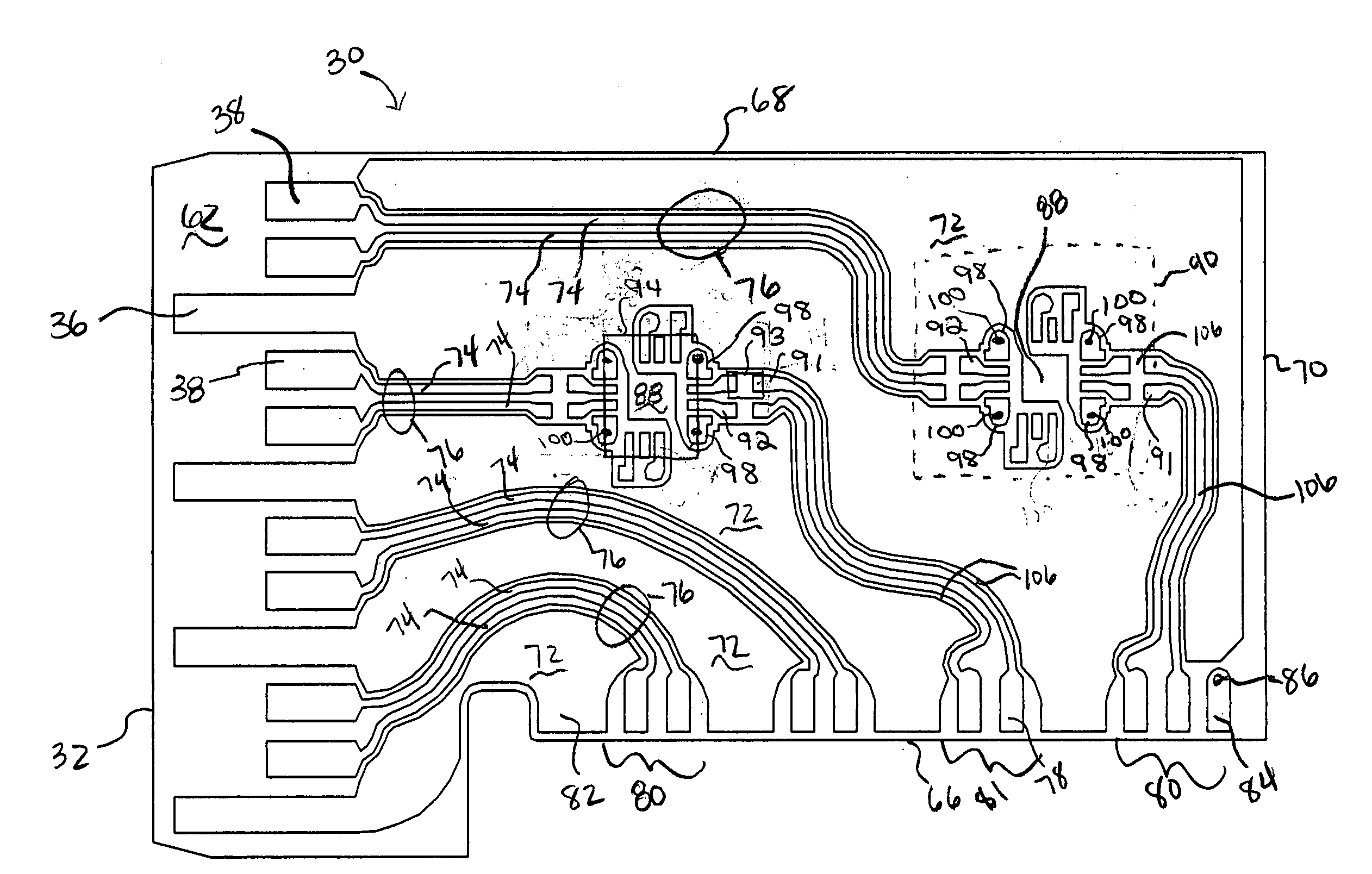
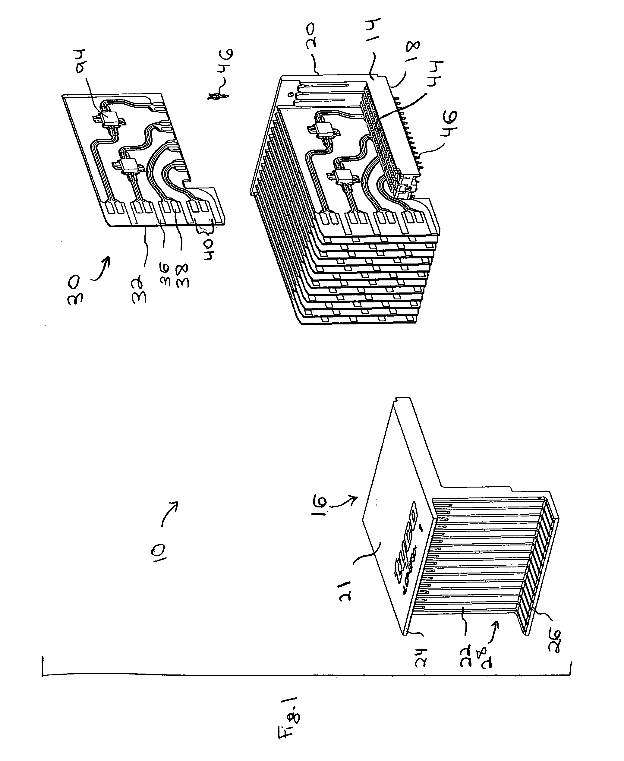
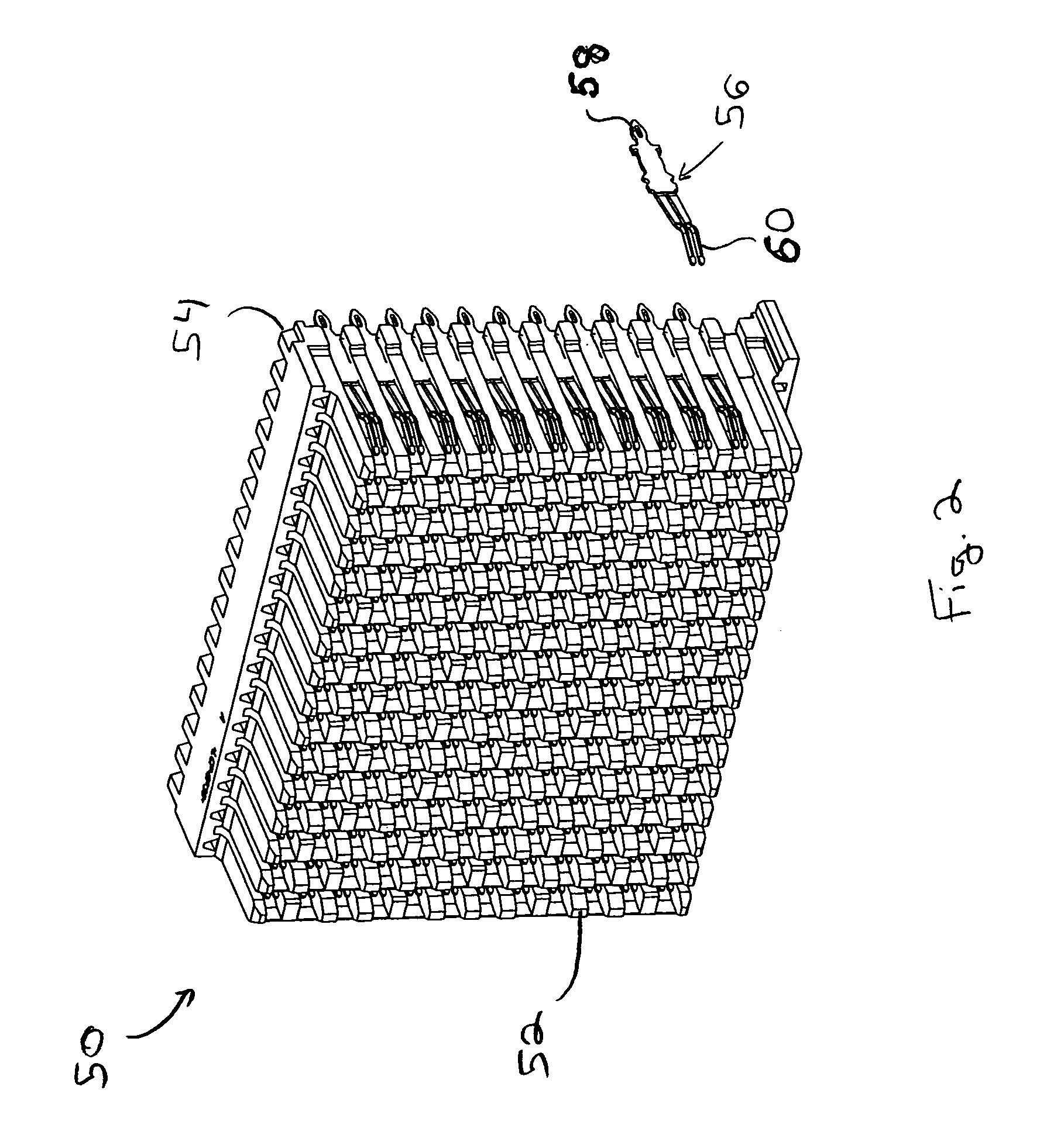
[0017]FIG. 1 illustrates a connector assembly 10 formed in accordance with an embodiment of the present invention. The connector assembly 10 includes a housing which includes an L-shaped frame 14 and an h-shaped cover 16 that mate with one another. The frame 14 includes a lower face that defines a daughter card interface 18 formed integrally with a backwall 20. The cover 16 comprises a top wall 21 formed integrally with a front wall defining a backplane assembly interface 22. The backplane assembly interface 22 includes upper and lower flanges 24 and 26 extending outward from the backplane assembly interface 22 to define a contact mating area (generally denoted by reference numeral 28). The frame 14 and cover 16 receive and retain a plurality of cards or wafers30 which are arranged parallel to one another and spaced apart from one another. Optionally, the wafers 30 may be separated by ground shields (not shown). Each wafer 30 includes an edge defining a backplane edge 32 which exten...


PUM


Abstract

An electrical connector is provided for operation in a point-to-point application. The connector includes an insulated housing having first and second card interfaces configured to mate with associated first and second circuit cards. An electrical wafer is held in the housing and configured to operate in a point-to-point architecture. The signal traces end at signal contact pads located proximate to first and second edges, respectively. The signal contact pads receive a unidirectional signal. Each of the signal traces include a break section at an intermediate point along a length thereof to form a disconnect in the signal traces. The connector further includes an active compensation component bridging the break section in the signal traces. The active compensation component compensates the differential signal incoming from the input contact pads for signal degradation and transmits a compensated signal outward to the output contact pads. The active compensation component transmits the signal only in a single direction within the point-to-point architecture.

Description

BACKGROUND OF THE INVENTION[0001]Embodiments of the present invention generally relate to an electrical connector for use with point-to-point serial data streams and particularly to connectors that compensate for signal loss within point-to-point data streams.[0002]In the past, right angle connectors have been provided for connection between printed circuit boards. The right angled connectors may use a large plurality of receiving terminals oriented at a right angle to an equally large plurality of pins. One common implementation of such connectors is to join daughter cards with a backplane in a data transmission system. In conventional systems, connectors have been proposed that are able to support bi-directional data streams arranged in a multi-drop bus configuration. These conventional bi-directional data streams conveyed signals in opposite directions over each individual trace through the connector.[0003]Existing multi-drop bus architectures utilize a single driver or transmitt...

Claims


Application Information

Patent Timeline
IPC IPC(8): H01R13/66
CPCH01R13/6658H01R12/727
Inventor ROTHERMEL, BRENT RYANMORGAN, CHAD WILLIAMSHARF, ALEX MICHAELHELSTER, DAVID WAYNE
Owner TYCO ELECTRONICS LOGISTICS AG (CH)
Why Eureka
Try Eureka