Abrasive tool inserts with diminished residual tensile stresses and their production

a residual tensile stress and tool insert technology, applied in the field of abrasive tool inserts, can solve the problems of tool delamination failure, fracturing of the layer, brittleness of the abrasive compact, etc., and achieve the effect of reducing the residual tensile stress in the abrasive layer

Inactive Publication Date: 2005-08-23
GE SUPERABRASIVES
View PDF18 Cites 64 Cited by
  • Summary
  • Abstract
  • Description
  • Claims
  • Application Information

AI Technical Summary

Benefits of technology

[0012]The present invention relates to an abrasive tool insert which comprises a substrate having a support face that includes: an inner support table; an outer shoulder having a width, Sw; a downwardly sloping interface from the support table to the shoulder which interface has a slope angle, Sa; and a continuous abrasive layer integrally formed on the substrate support face, which abrasive layer includes: (a) a center having a height, Dc; (b) a diameter, Dd; (c) a periphery having a height, Dp, in contact with the shoulder and which periphery forms a cutting edge; wherein, (i) Sw:Dd ranges from between 0 and about 0.5; and (ii) for each Sa and Sw:Dd, Dc:Dp is selected so as to diminish residual stress in the abrasive layer.

Problems solved by technology

Abrasive compacts tend to be brittle and, in use, they frequently are supported by being bonded to a cemented carbide substrate.
Another potential shortcoming relates to the creation of internal stresses within the diamond layer, which can result in a fracturing of that layer.
In some applications, the tools are subject to delamination failures caused by thermally induced axial residual stresses on the outer diameter of the superabrasive layer.
The stresses reduce the effectiveness of the tools and limit the applications in which they can be used.

Method used


Image

  • Abrasive tool inserts with diminished residual tensile stresses and their production
  • Abrasive tool inserts with diminished residual tensile stresses and their production
  • Abrasive tool inserts with diminished residual tensile stresses and their production

Examples


examples

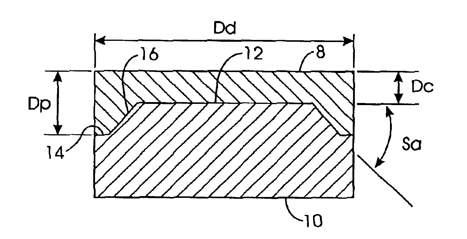
[0065]Applicants have performed finite element analysis (FEA) of the inventive cutter versus the prior art polycrystalline diamond cutters (having a flat interface). The cutters are manufactured by conventional high pressure / high temperature (HP / HT) techniques well known in the art. Such techniques are disclosed, inter alia, in the art cited above. The prior art cutter has a flat interface, 19 mm diameter, 16 mm overall height, 3 mm diamond table thickness. The cutter of the invention has an optimized interface of slope angle of 45°,a height ratio of 0.6,and a shoulder width ratio=0.025.FEA results are shown in Table 1.

[0066]

TABLE 1Flat Inter-InventiveStress in MPaface CutterCutterMaximum Surface Tensile Axial Stress59558Maximum Surface Tensile Radial Stress300110Maximum Surface Tensile Hoop Stress880

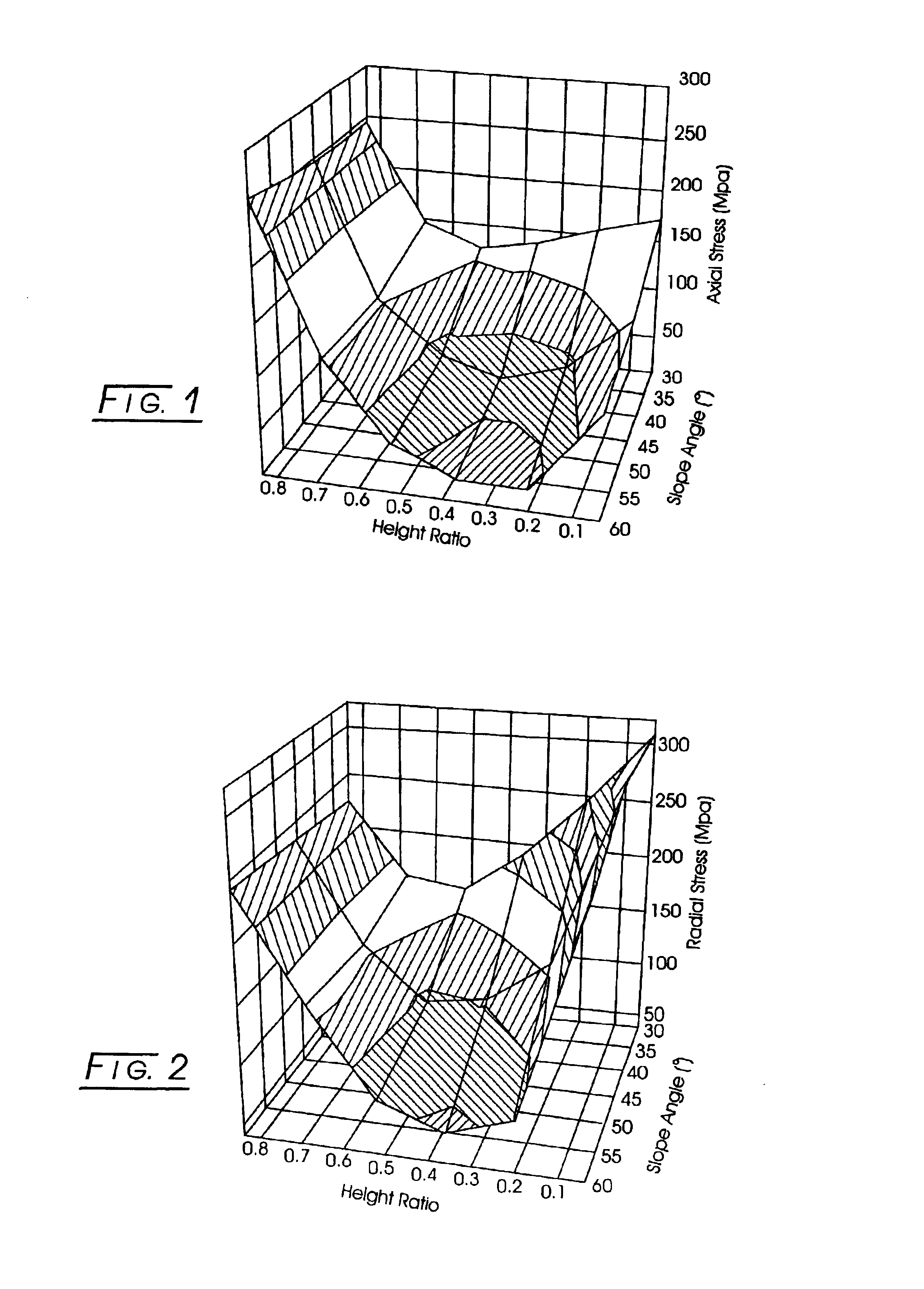
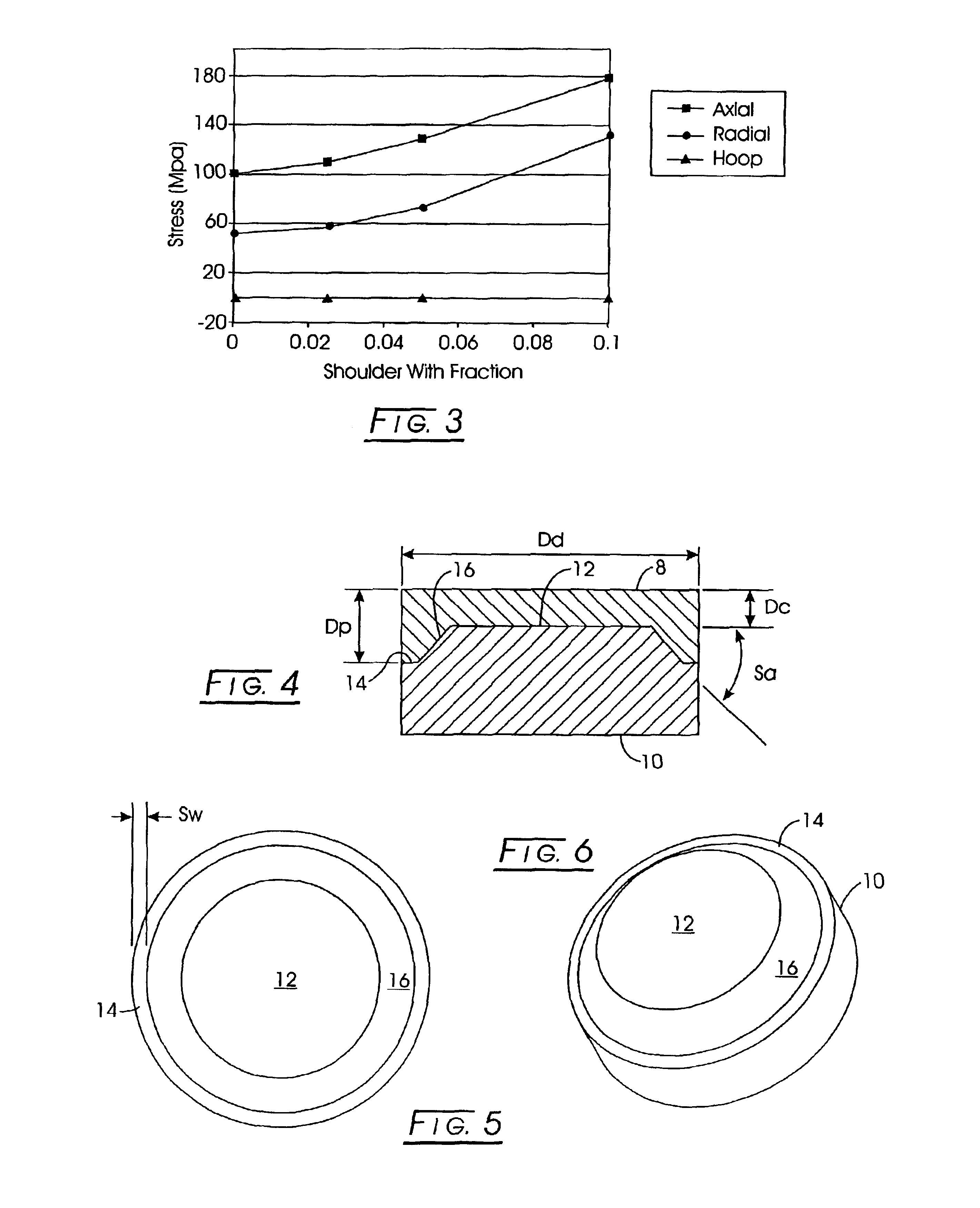
[0067]The foregoing results can be extended to additional table diameters, diamond table heights, slope angles, and shoulder widths. Table 2 display correlations of shoulder angle (Sa) ...


PUM

PropertyMeasurementUnit
diameteraaaaaaaaaa
heightaaaaaaaaaa
slope angleaaaaaaaaaa

Abstract

An abrasive tool insert includes (a) a substrate having a support face that includes (1) an inner support table, (2) an outer shoulder having a width, Sw, and (3) a downwardly sloping interface from the support table to the shoulder, which interface has a slope angle, Sa. A continuous abrasive layer, integrally formed on the substrate support face, includes (1) a center having a height, Dc, (2) a diameter, Dd, (3) a periphery having a height, Dp, in contact with the shoulder and which periphery forms a cutting edge. Sw:Dd ranges from between 0 and about 0.5. For each Sa and Sw:Dd, Dc:Dp is selected so as to diminish residual stress in the abrasive layer.

Description

CROSS-REFERENCE TO RELATED APPLICATIONS[0001]This application claims priority on U.S. Provisional Application Ser. No. 60 / 395,182, filed on Jul. 10, 2002.FIELD OF THE INVENTION[0002]The present invention relates to the field of abrasive tool inserts and, more particularly, to such inserts having minimized residual tensile stresses.BACKGROUND OF THE INVENTION[0003]Abrasive compacts are used extensively in cutting, milling, grinding, drilling and other abrasive operations. An abrasive particle compact is a polycrystalline mass of abrasive particles, such as diamond and / or cubic boron nitride (CBN), bonded together to form an integral, tough, high-strength mass. Such components can be bonded together in a particle-to-particle self-bonded relationship, by means of a bonding medium disposed between the particles, or by combinations thereof. The abrasive particle content of the abrasive compact is high and there is an extensive amount of direct particle-to-particle bonding. Abrasive compa...

Claims


Application Information

Patent Timeline
Patent Type & Authority Patents(United States)
IPC IPC(8): E21B10/46E21B10/56E21B10/573
CPCE21B10/5735Y10T428/30
Inventor WAN, SHANO'TIGHEARNAIGH, EOIN M.RAFTERY, THERESESNYDER, ROSEMARIE SHELLYFLOOD, GARY MARTIN
Owner GE SUPERABRASIVES
Why Eureka
Try Eureka