
Organic electroluminescent device and method for producing the same

a light-emitting device and electroluminescent technology, applied in thermoelectric devices, discharge tubes/lamp details, discharge tubes luminescnet screens, etc., can solve the problems of reducing the luminescence efficiency of the triplet phosphorescence under high-density current, the final object of projecting white light of full color cannot be achieved, and the triplet energy transfer originated from the conductive host material, etc., to achieve the effect of effective raising luminescence efficiency and service life,

Inactive Publication Date: 2005-08-23
OPTO TECH
View PDF1 Cites 45 Cited by
  • Summary
  • Abstract
  • Description
  • Claims
  • Application Information

AI Technical Summary

Benefits of technology

[0010]Accordingly, it is a primary object of the present invention to provide an organic electroluminescent device capable of obtaining the best even distribution of light color so as to readily achieve the final product requirement for white light and full-coloredness by means of three-wavelength projection light source.
[0011]It is a secondary object of the present invention to provide an organic electroluminescent device capable of solving the drawback with respect to the production of white light source or full-colored product for a ling time.
[0012]It is another object of the present invention to provide an organic electroluminescent device for effectively raising luminescence efficiency and service life by cooperating the host material with and guest luminous substance.
[0013]It is still another object of the present invention to provide an organic electroluminescent device being not only non-wasting the triplet exciton but also raising luminescence efficiency by means of effectively utilizing the triplet exciton with the most significant percentage.

Problems solved by technology

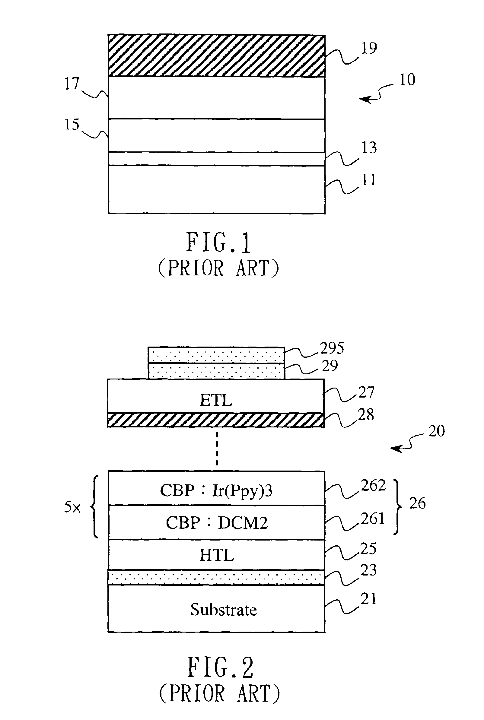
The projection light source may be obtained via the structure and technology of the first conventional OLED described above, however, only a monochromatic light could be projected, and the final object of projecting white light of full-coloredness could not be achieved.
Moreover, although light in the organic electroluminescent device may be presented as two types including singlet fluorescence and triplet phosphorescence, most of the guest luminous substances in the conventional organic electroluminescent device may be adapted to utilize the fluorescent dye substance of the former, and ignoring the latter, due to the physical characteristics that the exciton of the triplet phosphorescence could not be radiatively released, that the luminescence thereof is slow and insufficient, that the triplet energy transfer originated from the conductive host material layer to the guest luminous substance is slower than the singlet one, and that the luminescence efficiency of the triplet phosphorescence my be decreased rapidly under the high-density current.
As such, if the white light source or full-colored product requirement is necessary, not only the uncontinuous light source, but also light color uneveness or color bias phenomenon (green bias or red bias) may be liable to occur, thus, not suitable for being the choice for white light source or full colored product.
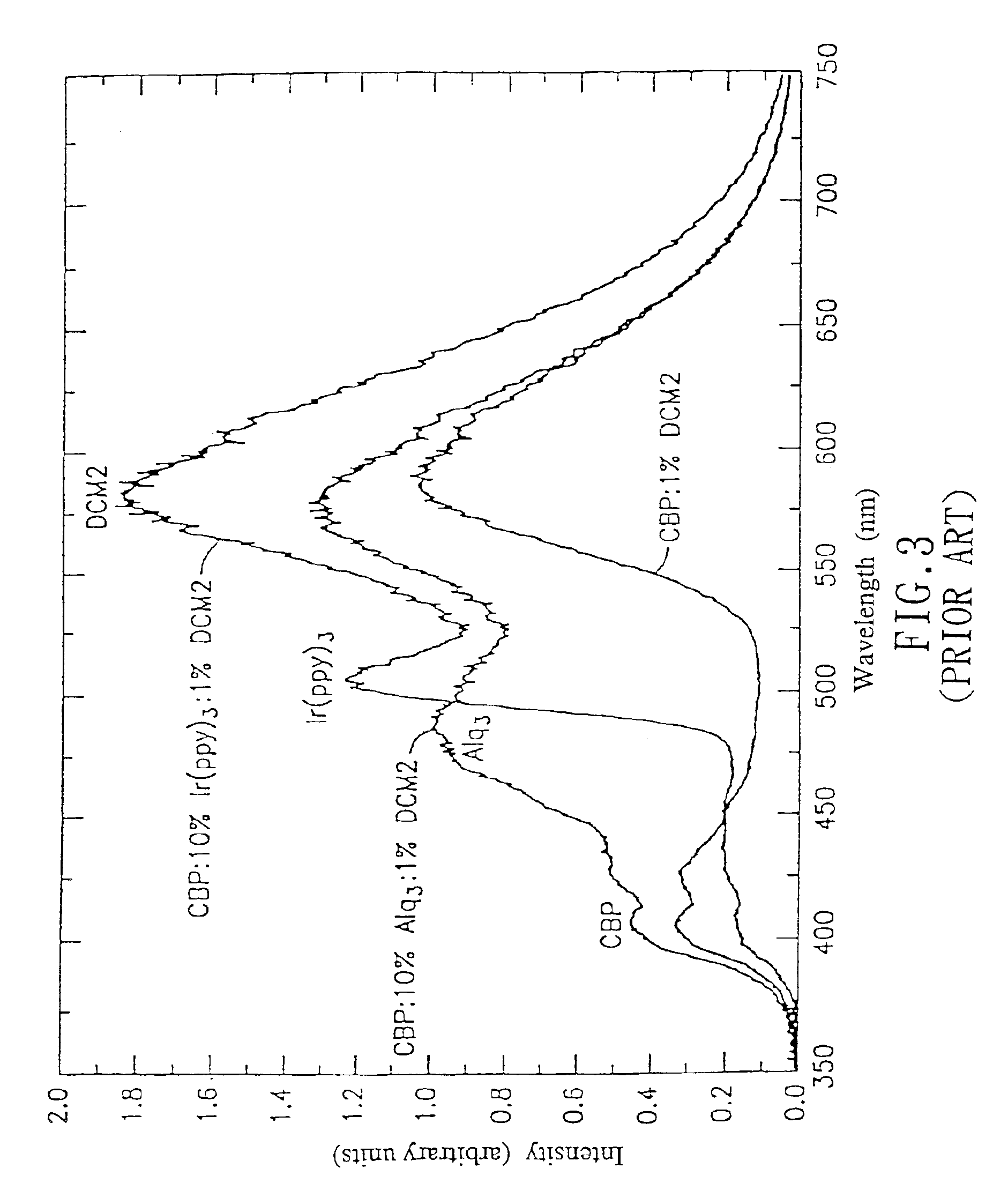
However, disadvantages of light uneveness or color bias phenomenon, how to get the white light source and raise the luminescence efficiency, and difficulty in obtaining pure color from the red source as well as shorter service life may be presented in the aforementioned approaches, respectively.
In particular, all of them are pertained to two-wavelength luminescence approach, thus not suitable for the white light source and full-colored product requirement.

Method used


Image

  • Organic electroluminescent device and method for producing the same
  • Organic electroluminescent device and method for producing the same
  • Organic electroluminescent device and method for producing the same

Examples


Embodiment Construction

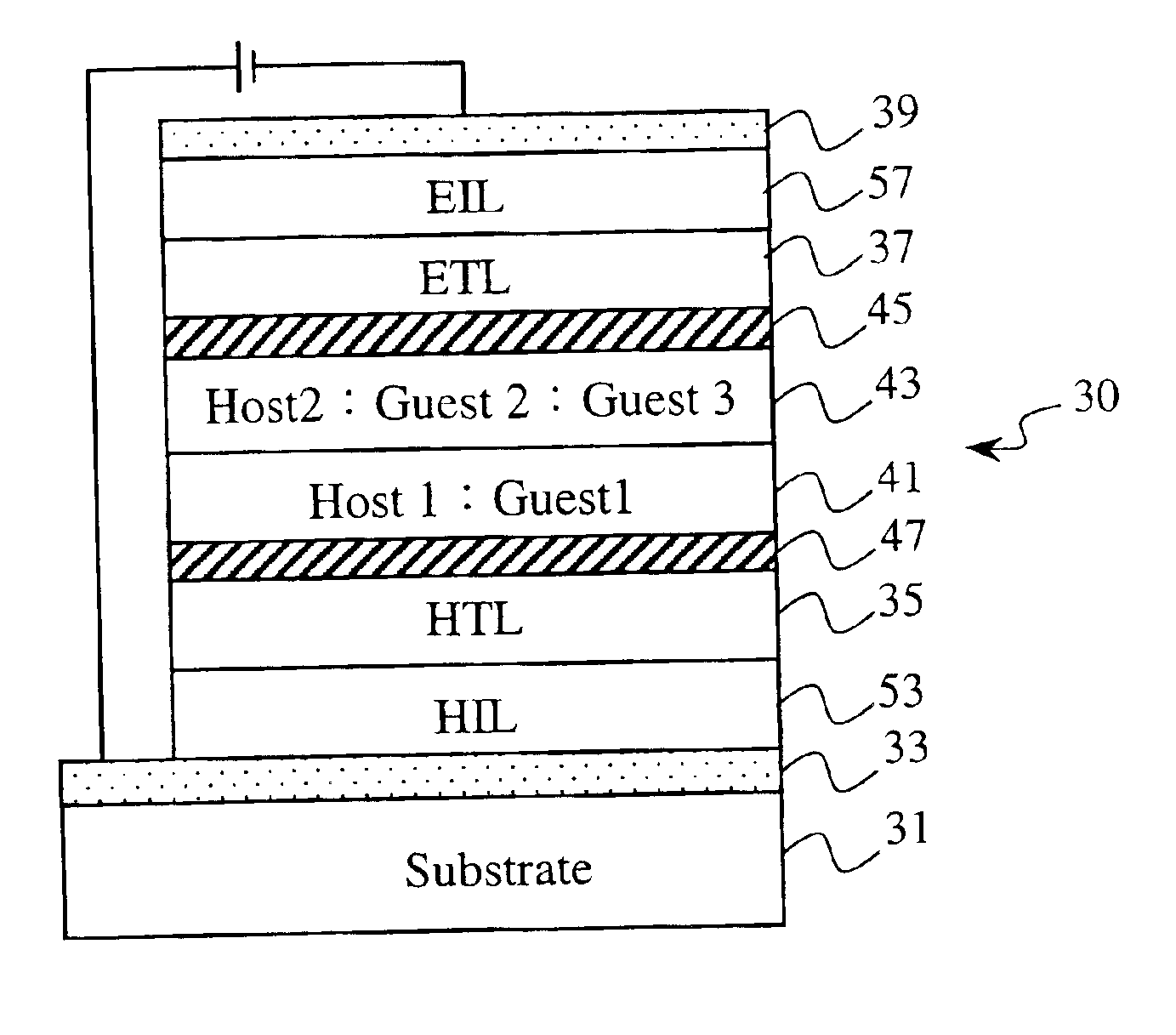
[0019]Firstly, referring to FIG. 4, there is shown a structural cross-section view of one embodiment of the present invention. As illustrated in this figure, an organic electroluminescent device 30 of the present invention essentially comprising forming a first conductive layer 33 (for example, anode) onto the top side of a light-transparent substrate 31 by vapor deposition, sputtering deposition, and so on, Subsequently, onto the top side of the anode 33, there may be formed with, in turn, a hole injecting layer 53 (HIL; first carrier injecting layer), a hole transporting layer 35 (HTL; first carrier transporting layer), and an electron blocking layer 47 for blocking the second carrier (electron) to proceed. Onto the top side of the electron blocking layer 47, there may be then further formed with, in turn, a first host material layer 41 (Host 1) and a second host material layer 43 (Host 2), and the top side of the second host material layer 43 may be further formed with a hole blo...


PUM


Abstract

An organic electroluminescent device with the feature of three-wavelength luminescence is provided. The device includes a hole transporting layer, an electron blocking layer, a first host material layer, a second host material layer, a hole blocking layer, and an electron transporting layer placed between an anode and a cathode in turn. In which, the first host material layer has a first guest luminous substance mixed therein for projecting a first color light source (B), while the second host material layer correspondingly has a second guest luminous substance and a third guest luminous substance mixed therein for projecting a second color light source (G) and a third color light source (R), respectively, under the effect of an external bias voltage, wherein said second guest luminous substance or said third guest luminous substance may be a phosphorescence substance. Thus, not only a continuously full-band, full-colored light source featuring three-wavelength may be acquired directly by means of the combination of RGB colors, but also an effective utilization of phosphorescence substance and thus significantly raised luminescence efficiency may be obtained.

Description

FIELD OF THE INVENTION[0001]The present invention is related to a light-emitting device, particularly to an organic electroluminescent device with the feature of white light emitted by three-wavelength and a method for producing the same.BACKGROUND[0002]An organic electroluminescent device (OLED), presented by C. W. Tang and S. A. VanSlyke, Kodak Company in 1987, is made by vacuum vapor deposition method for depositing a hole-transporting material and an electron-transporting material, such as Alq3, onto a light-transparent indium-tin oxide (ITO) glass, respectively, and then vapor depositing a metal electrode, to form an organic electroluminescent device (OLED) with self-luminescence, fast response speed, light weight, thin thickness, low power consumption, large view angle, high brightness, and full-coloredness. Thereafter, the organic electroluminescent device has been considered as a star product in the monitor industry or to project white light by all circles, in order to achie...

Claims


Application Information

Patent Timeline
IPC IPC(8): H01L51/50H01L51/05H01L51/30H05B33/14H01L51/00
CPCH01L51/5036H01L51/005H01L51/0059H01L51/0078H01L51/0081H01L51/0084H01L51/0085H01L51/5016H01L51/5096H10K85/60H10K85/631H10K85/311H10K85/324H10K85/341H10K85/342H10K50/11H10K2101/10H10K50/125H10K50/18H10K50/181H05B33/14
Inventor LIN, MING-DERCHUANG, FENG-JUJOU, JWO-HUEIHUANG, YEN-SHIH
Owner OPTO TECH
Learn More