Method and apparatus of detecting disturbances in a centrifugal pump

a centrifugal pump and disturbance detection technology, applied in the field of centrifugal pumps, can solve the problems of difficult condition monitoring and early detection of defects, difficult to detect defects, and often fall or be unpractical for shaft vibration sensors, etc., to achieve easy identification of healthy operations.

Inactive Publication Date: 2005-08-23
EATON INTELLIGENT POWER LTD
View PDF21 Cites 105 Cited by
  • Summary
  • Abstract
  • Description
  • Claims
  • Application Information

AI Technical Summary

Benefits of technology

[0008]Accordingly, motor power is used to determine the presence of a mechanical interference in the pump, i.e. a misaligned shaft, impeller damage, and debris. Power is preferably determined from voltage and current data acquired from a three-phase motor. At initial setup of the pump assembly, a baseline signal is determined from the pump known to be operating in a normal, healthy condition. The baseline signal or data is then used for comparison with instantaneous power signals so that deviations from normal, healthy operation can be readily identified.
[0009]Voltage and current data are collected for a relatively short period of time such as one second and a corresponding power signal is then generated. The power signal is then analyzed with a fast Fourier transform (FFT) to locate discrete frequency peaks that are related to rotational frequency. The amount of second harmonic of power frequency expected due to the voltage and current unbalance is then estimated and used as a check on power quality. By comparing the transformed signal with the baseline signal, spectral peaks indicative of undesirable or unexpected harmonics may be readily identified. Once the peaks are located, the magnitude of the peaks is also observed as an indication of the magnitude of the mechanical disturbance. Preferably, a maintenance warning or flag is then provided to an operator or other technician so that, if needed, the pump may be shut down and repaired.
[0010]Therefore, in accordance with one aspect of the present invention, a motor control for a motor-driven pump is provided. A controller includes at least one voltage sensor and at least one current sensor and is configured to receive a voltage and a current signal of the pump in operation from the at least one voltage sensor and at least one current sensor. The controller is further configured to determine a power signal from the voltage signal and the current signal and generate a real-time spectrum analysis of the power signal. The controller is also configured to determine undesirable torque or motor rotor displacement conditions in the pump from the spectrum analysis.
[0011]In accordance with another aspect of the present invention, a computer readable storage medium having stored thereon a computer program to detect and signal mechanical anomalies in a motor-driven pump is provided. The computer program represents a set of instructions that when executed by a processor causes the processor to determine an instantaneous pump motor power signal from voltage and current data collected by one or more voltage and current sensors in the motor of the motor-driven pump. The set of instructions further causes the processor to signal process the instantaneous pump motor power signal and compare the processed signal to a pump motor power signal modeled from healthy operation of the pump motor. The computer program then determines whether harmonics of the instantaneous pump motor signal exceed a threshold and if so provides an external notification signaling the presence of mechanical anomalies in the pump.

Problems solved by technology

Moreover, motor power can exceed 2,000 kW and voltages over 10,000 V. As a result of the remote location of these pumps, condition monitoring and detection of defects at an early state are often difficult.
For example, sensors for shaft vibration often fall or are not practical as they cannot efficiently withstand high ambient water pressure.
Additionally, signal cables may be used to translate signals to a surface monitoring device but the cables are often damaged during pump installation to a deep well.
As power consumption of the pumps change widely with operation point, the pump protectors have to be adjusted rather insensitively so that small changes in motor current caused, for example, by worn out bearings are not detected.
Mechanical disturbances or interference in motor / centrifugal pump assemblies may be caused by several conditions.
For example, severe bearing deterioration may result in binding of deteriorated balls of the bearing or of rubbing in the area between wear rings and the pump rotor.
In close-coupled pumps touchdown of a motor rotor to the stator may occur resulting in mechanical disturbances.
Shaft misalignment or bent shafts may also create interference through vibration and torque ripple.
Debris which may be lodged in or around the pump impeller may also create mechanical interference.
Moreover, loose impeller or unstable foundation may also create interference and disrupt proper operation of the pump.
Because of the location of the submersible pump during operation, it is typically difficult to detect the onset of a mechanical disturbance.
This additional instrumentation, however, adds to the cost of the pump and damage to the cables often occurs when placed in a deep well.
Pump failure may result in severe economic loss due to unscheduled plant shutdown and the attendant cleanup and restart required after unscheduled shutdown.
However, the installation cost of in-place monitoring is high and the skilled labor associated with periodic testing is costly.

Method used


Image

  • Method and apparatus of detecting disturbances in a centrifugal pump
  • Method and apparatus of detecting disturbances in a centrifugal pump
  • Method and apparatus of detecting disturbances in a centrifugal pump

Examples


Embodiment Construction

[0020]The present invention is related to the detection of abnormal conditions as a result of mechanical interference in a centrifugal pump. However, the present invention is equivalently applicable to the detection of undesirable conditions in other types of motor-driven pumps. Abnormal conditions or disturbances include but are not limited to interference caused by impeller damage, shaft misalignment, lodged debris, seal failure, bearing failure, and ring wear.

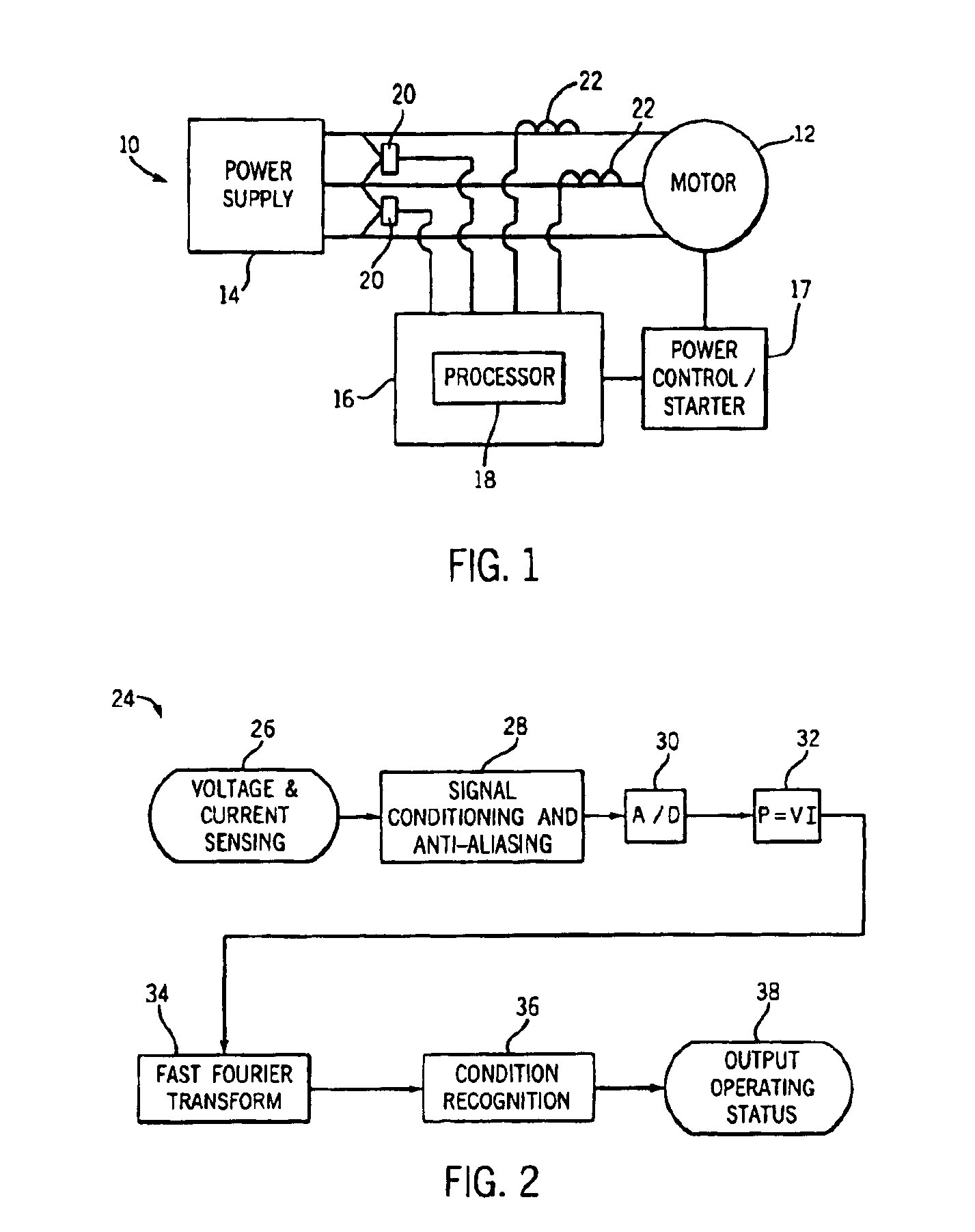
[0021]Referring now to FIG. 1, a motor assembly such as an induction motor for a centrifugal pump is shown. Motor assembly 10 includes a motor 12 that receives power from a power supply 14. The assembly also includes a controller 16 used to monitor as well as control operation of the motor in response to operator inputs or motor overloads. The motor and controller assembly typically include either contacts or electronic devices as a power control 17 in series with the motor supply to control power to the motor. These contact...


PUM


Abstract

The present invention is directed to a centrifugal pump wherein voltage and current data are detected from voltage and current sensors in the motor controller of a pump motor. A power signal is then generated from the voltage and current data and spectrally analyzed to determine the presence of unwanted harmonics which are indicative of mechanical disturbances in the pump. As such, anomalies resulting from mechanical interference may be detected and a warning flag provided without additional transducers and other instruments on the motor or pump.

Description

BACKGROUND OF INVENTION[0001]The present invention relates generally to centrifugal pumps, and more particularly, to a method and apparatus of detecting torsional disturbances or alternately mechanical disturbances that cause displacement of the motor's rotor in a centrifugal pump assembly using voltage and current data acquired from voltage and current sensors in the pump motor controller assembly.[0002]Submersible types of centrifugal motor pumps are used for a number of applications, such as drinking water supply, irrigation, and de-watering as well as in offshore applications. In these applications and others, the motor as well as the pump may be submerged and installed in deep wells down to several thousand meters. Moreover, motor power can exceed 2,000 kW and voltages over 10,000 V. As a result of the remote location of these pumps, condition monitoring and detection of defects at an early state are often difficult. For example, sensors for shaft vibration often fall or are no...

Claims


Application Information

Patent Timeline
Patent Type & Authority Patents(United States)
IPC IPC(8): F04D15/02G01M99/00F04B49/06
CPCF04B49/065F04D15/0209
Inventor SCHUCHMANN, RUSSELL P.
Owner EATON INTELLIGENT POWER LTD
Why Eureka
Try Eureka