
System and method for measuring optical distance

Inactive Publication Date: 2005-08-23
MASSACHUSETTS INST OF TECH
View PDF32 Cites 39 Cited by
  • Summary
  • Abstract
  • Description
  • Claims
  • Application Information

AI Technical Summary

Benefits of technology

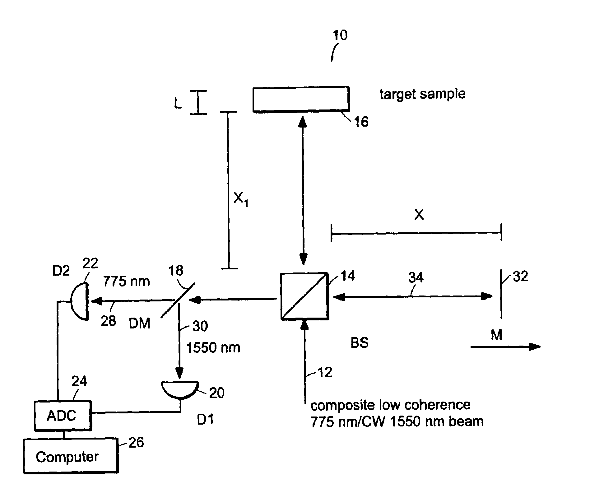
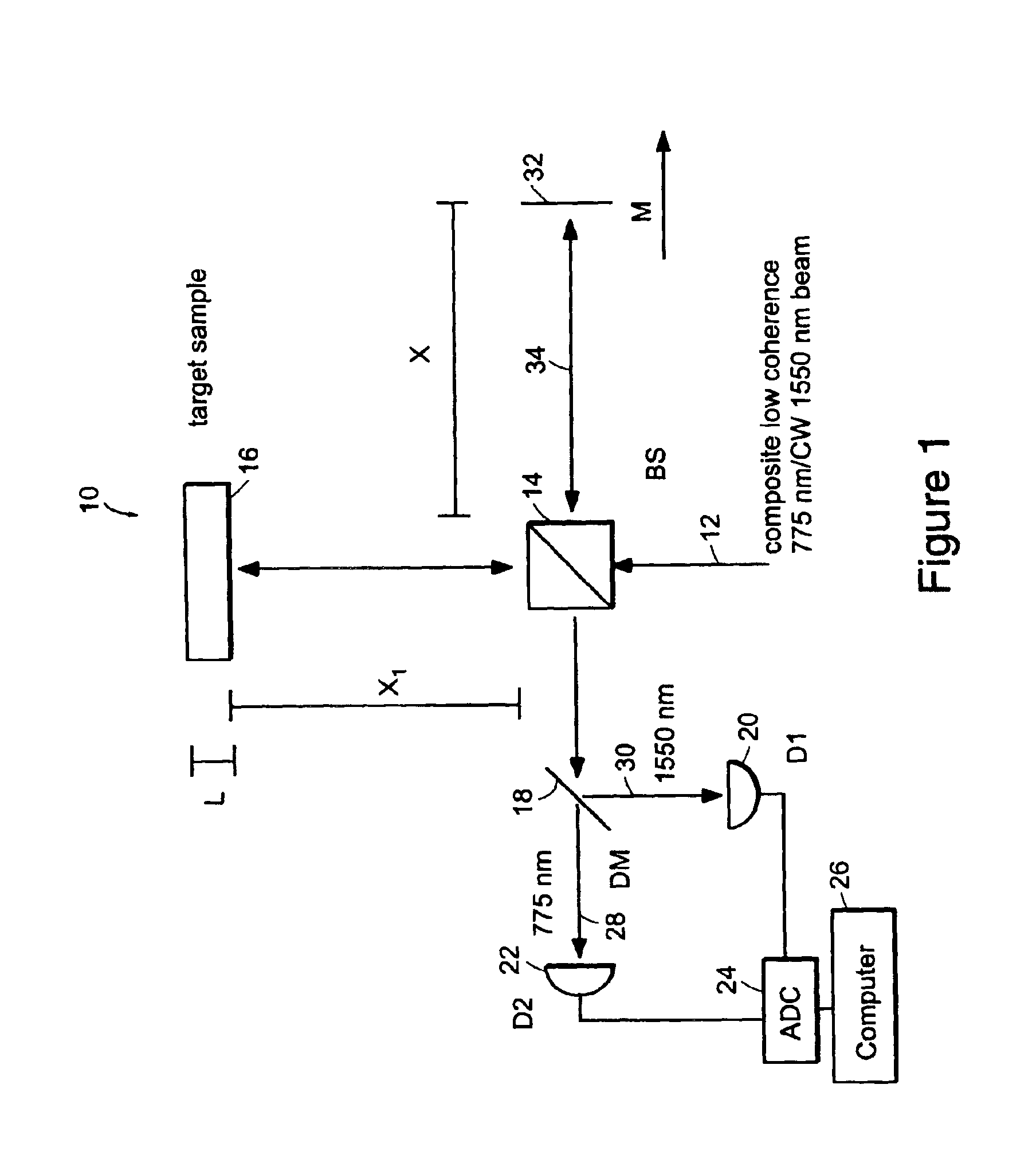
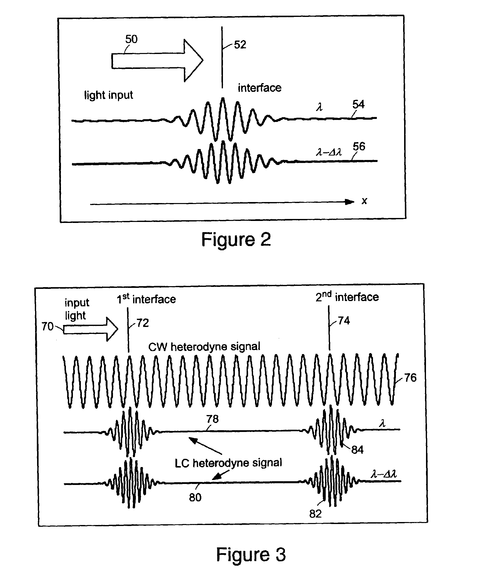
[0004]The methods of the present invention are directed at an accurate phase-based technique for measuring arbitrarily long optical distances, preferably with sub-nanometer precision. A preferred embodiment of the present invention employs an interferometer, for example, a Michelson interferometer, with harmonically related light sources, one continuous wave (CW) and a second source having low coherence (LC). The low coherence source provides a broad spectral bandwidth, preferably a bandwidth of greater than 5 nm for a 1 micron (μ) wavelength, for example, the required bandwidth can vary as a function of wavelength and application. By slightly adjusting the center wavelength of the low coherence source between scans of the target sample, the phase relationship between the heterodyne signals of the CW and low coherence light can be used to measure the separation between reflecting interfaces with sub-nanometer precision. As this technique is completely free of 2π ambiguity, an issue that plagues most phase-based techniques, it can be used to measure arbitrarily long optical distances without loss of precision. An application of a preferred embodiment of the method of the present invention is the precision determination of the refractive index of a sample at a given wavelength of a sample with a known physical thickness. Another application of a preferred embodiment of the method of the present invention is the precision determination of a sample's physical thickness with a known refractive index. A further application of a preferred embodiment of the method of the present invention is the precision determination of the refractive index ratio at two given wavelengths.
[0006]The preferred embodiment methods can be used to make precise optical distance measurements. From such measurements, optical properties of target objects can be accurately measured. By measuring the dispersion profile of the target, structural and / or chemical properties of the target can be evaluated. The dispersion profile maps out the refractive index differences at various wavelengths. In the biomedical context, preferred embodiments of the present invention can be used to accurately determine the dispersion properties of biological tissues in a non-contact and non-invasive manner. Such dispersion determination can be used on the cornea or aqueous humor of the eye. The sensitivity achieved can be sufficient to detect glucose concentration dependent optical changes. In a preferred embodiment of the present invention method, the blood glucose level can be determined through non-invasive measurements of the dispersion profile of either the aqueous, vitreous and / or aqueous and / or aqueous humor or the cornea of the eye. A preferred embodiment of the present invention can be applied as a measurement technique in semiconductor fabrication to measure small features formed during the manufacturing of integrated circuits and / or optoelectronic components. As the preferred embodiment of the method is non-contact and non-destructive, it can be used to monitor the thickness of semiconductor structures or optical components as they are being fabricated.

Problems solved by technology

However, most such techniques are limited by an issue which is widely known in the field as 2π ambiguity or integer ambiguity which can be defined as the difficulty in telling the interference fringes of an axial scan apart from each other.
While such a measurement approach works well in a controlled environment, it can hardly be implemented in a situation where there is less manipulability in the sample.
For example, the method does not work on a fixed slab of material which we are constrained to keep whole.
The problem lies in the fact that unmodified HPI is unable to tell the interference fringes of an axial scan apart from each other, described herein as the 2π ambiguity issue.
It is a problem that plagues most phase-based optical interferometric techniques.
As a result, these techniques are unable to determine optical distance absolutely.

Method used


Image

  • System and method for measuring optical distance
  • System and method for measuring optical distance
  • System and method for measuring optical distance

Examples


Embodiment Construction

[0018]The present invention is directed at phase crossing based systems and methods for measuring optical distances that overcome the integer or 2π ambiguity problem by introducing a dispersion imbalance in an interferometer. A preferred embodiment of the method is able to measure the relative height difference of two adjacent points on a surface with precision. Further, the refractive index of a sample can be found to an accuracy that is limited only by the precision with which the physical thickness of the sample can be experimentally measured.

[0019]The substitution of one of the low coherence light sources with a continuous wave (CW) light source in the harmonic phase based interferometry (HPI), allows the use of the associated CW heterodyne signal as a form of optical ruler by which the low coherence heterodyne signal can be measured. The low coherence light source provides a spectral bandwidth, for example, greater than 5 nm for 1 micron wavelength. One of the benefits of using...


PUM


Abstract

The methods of the present invention are directed at an accurate phase-based technique for measuring arbitrarily long optical distances with sub-nanometer precision. A preferred embodiment of the present invention method employs a interferometer, for example, a Michelson interferometer, with a pair of harmonically related light sources, one continuous wave (CW) and a second source having low coherence. By slightly adjusting the center wavelength of the low coherence source between scans of the target sample, the phase relationship between the heterodyne signals of the CW and low coherence light is used to measure the separation between reflecting interfaces with sub-nanometer precision. As the preferred embodiment of this method is completely free of 2π ambiguity, an issue that plagues most phase-based techniques, it can be used to measure arbitrarily long optical distances without loss of precision.

Description

GOVERNMENT SUPPORT[0001]The invention was supported, in whole or in part, by a Grant No. P41-RR02594 from the National Institutes For Health. The Government has certain rights in the invention.BACKGROUND OF THE INVENTION[0002]Phase-based optical interferometric techniques are widely employed in optical distance measurements in which sub-wavelength distance sensitivity is required. Optical distance is defined as the product of the refractive index and the length. However, most such techniques are limited by an issue which is widely known in the field as 2π ambiguity or integer ambiguity which can be defined as the difficulty in telling the interference fringes of an axial scan apart from each other. An unmodified harmonic phase based low coherence interferometry method (HPI) can be used to determine the differential optical distance, (nλ<sub2>2< / sub2>−nλ<sub2>1< / sub2>)L, where L is the physical distance, nλ<sub2>1 < / sub2>and nλ<sub2>2 < / su...

Claims


Application Information

Patent Timeline
IPC IPC(8): G01B9/02G01N21/45G01N21/41G01J9/00G01J9/04A61B3/10G01B11/00G01B11/02G01N21/17
CPCG01N21/45G01B9/02007G01B9/02002G01B9/0209G01B9/02078G01J9/04G01B2290/45
Inventor YANG, CHANGHUEIWAX, ADAMDASARI, RAMACHANDRA R.FELD, MICHAEL S.
Owner MASSACHUSETTS INST OF TECH
Learn More