Pressure fryer

a technology of pressure fryer and pressure pan, which is applied in the direction of fluid heater, light and heating apparatus, cooking vessels, etc., can solve the problems of difficult to adjust the amount of steam, difficult to obtain or maintain pressure, and difficult to achieve the effect of pressure gas and simple configuration

Active Publication Date: 2005-08-30
PALOMA
View PDF26 Cites 75 Cited by
  • Summary
  • Abstract
  • Description
  • Claims
  • Application Information

AI Technical Summary

Benefits of technology

[0010]According to a second aspect of the present invention, a pressure fryer is provided wherein the pressure gas is carbon dioxide. As a result, the pressure gas can be easily obtained or maintained.
[0011]According to a third aspect of the present invention, a pressure fryer further comprising a pressure detecting means for detecting pressure in the cooking container. The pressure gas supply is controlled according to a pressure value detected by the pressure detecting means and / or according to a rise gradient of the detected value. With this configuration, the pressure gas can be used efficiently.
[0012]Accordingly to a fourth aspect of the present invention, a pressure fryer is provided further comprising a timer means for counting the time elapsed from the start of cooking. A preset pressuring time for applying pressure is set according to a plurality of cooking menu options and pressure gas is supplied to the cooking container for the preset pressuring time according to the selected cooking menu. As a result, the desired pressure cooking can be carried out in a simple configuration using the pressure gas efficiently.

Problems solved by technology

On the other hand, when only a small amount of food is cooked, the application of pressure is conducted inadequately due to a lack of steam generated from moisture of the foods.
In this case, however, it is difficult to adjust the amount of the steam.
Due to this, the cooked foods can be damp because of excessive steam, or the cooking oil might suddenly boil due to water that is infused into the cooking oil.

Method used


Image

  • Pressure fryer
  • Pressure fryer
  • Pressure fryer

Examples


first embodiment

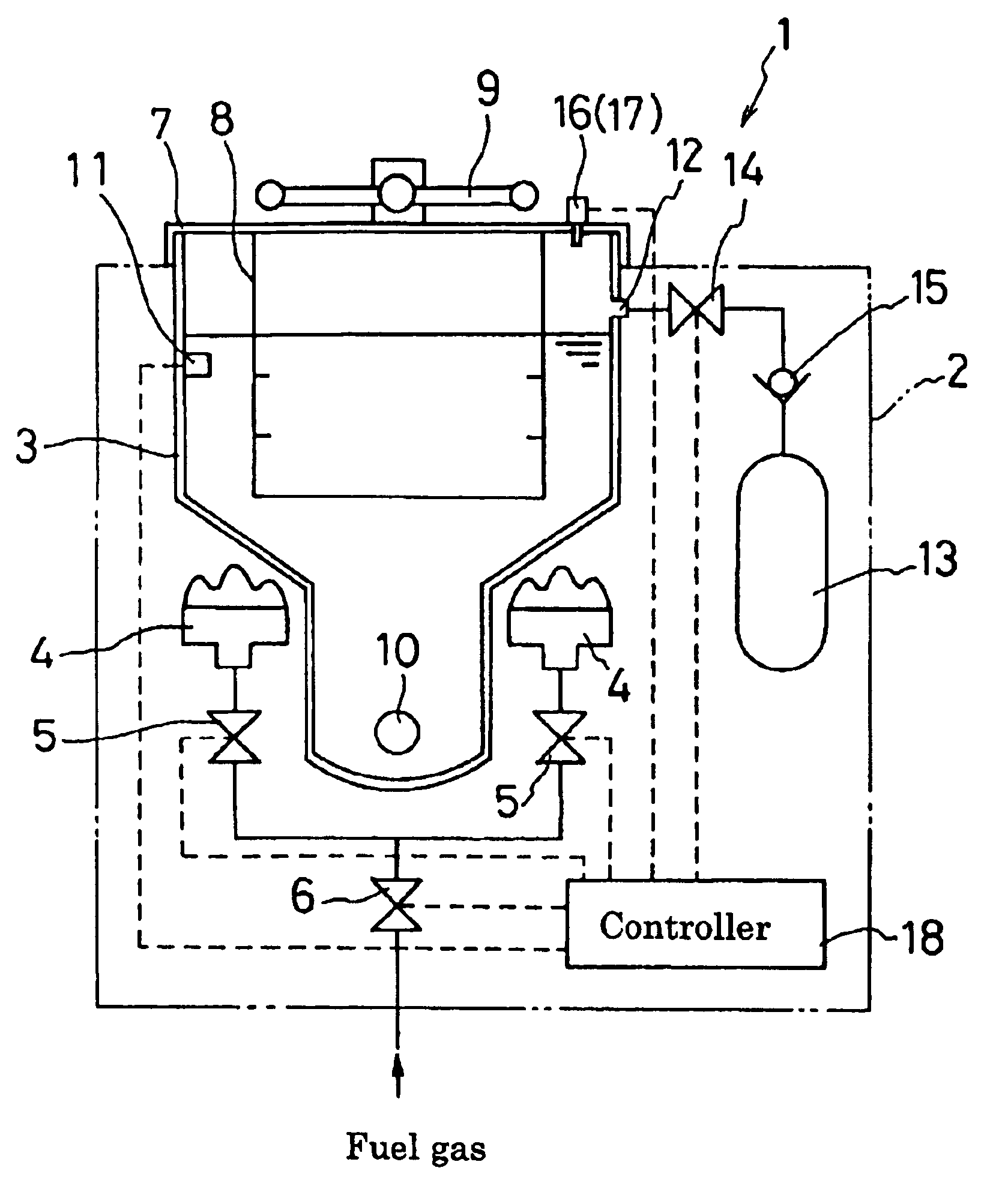
[0019]FIG. 1 shows a schematic view of an embodiment of a pressure fryer. A pressure fryer 1 has a casing 2, which includes a cooking container 3 for containing cooking oil, and burners 4, 4 for heating the cooking container 3 from the bottom. A burner electromagnetic valve 5 is provided with a gas conduit connected with each burner 4, and a main electromagnetic valve 6 is provided with an upstream gas conduit before being forked. On the top of the casing 2, a movable lid 7, which can hermetically seal an opening of the cooking container 3, is provided to be capable of upward and downward movement. On the bottom side of the lid 7, a basket 8 where foods can be disposed is positioned to be submerged in the cooking oil within the cooking container 3 with the lid 7 sealed. Reference number 9 indicates a handle to open or close the lid 7, reference number 10 indicates an oil drain provided on the bottom of the cooking container 3, and reference number 11 indicates an oil temperature sen...

second embodiment

[0027]Another embodiment of the present invention will be described below. A pressure fryer 1 of this embodiment has almost the same configuration as that of the first embodiment, with the only difference being that this embodiment does not have a pressure sensor. Therefore, explanations for the same configuration are omitted and a flow chart of the pressure cooking control will be only used for explanation.

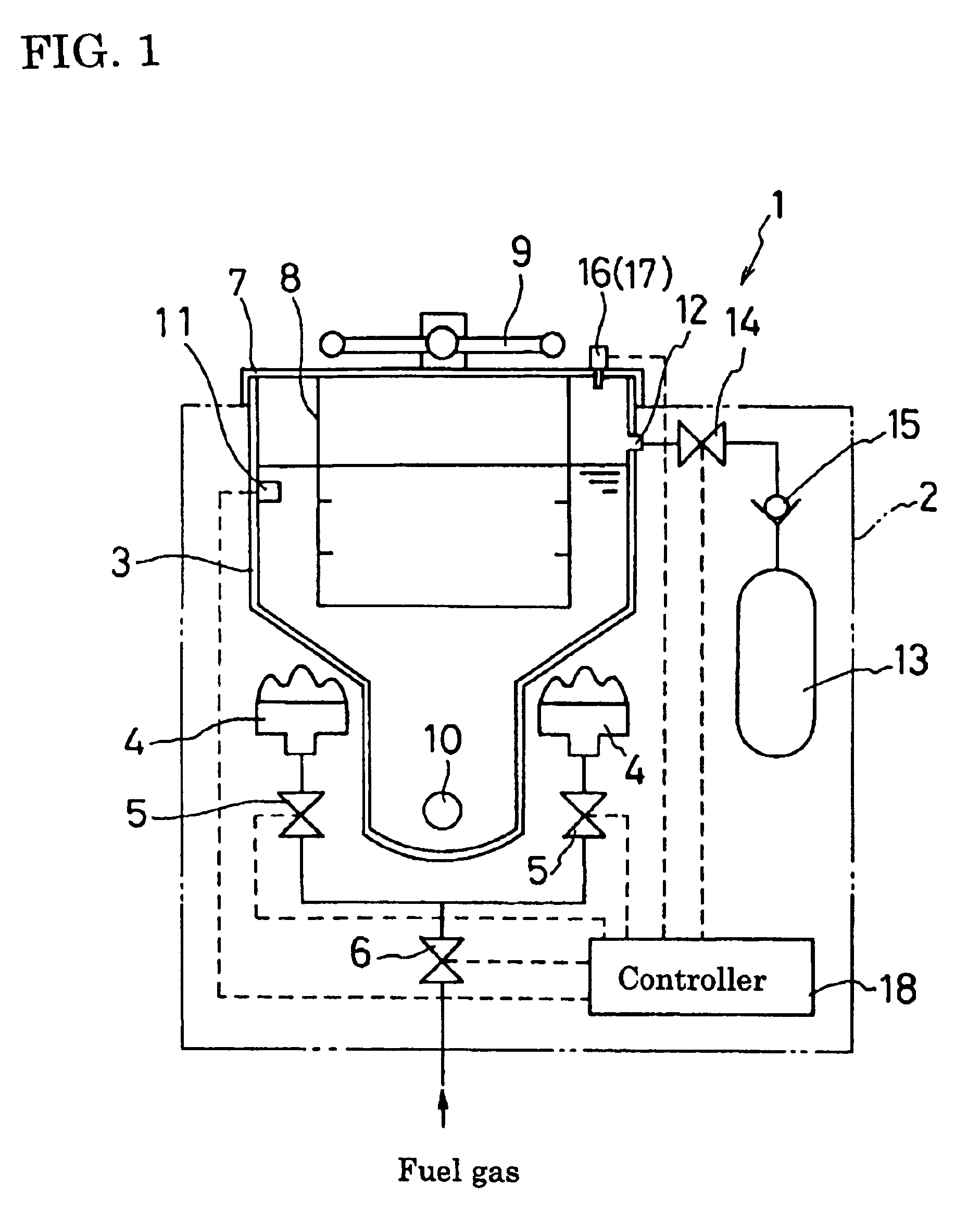
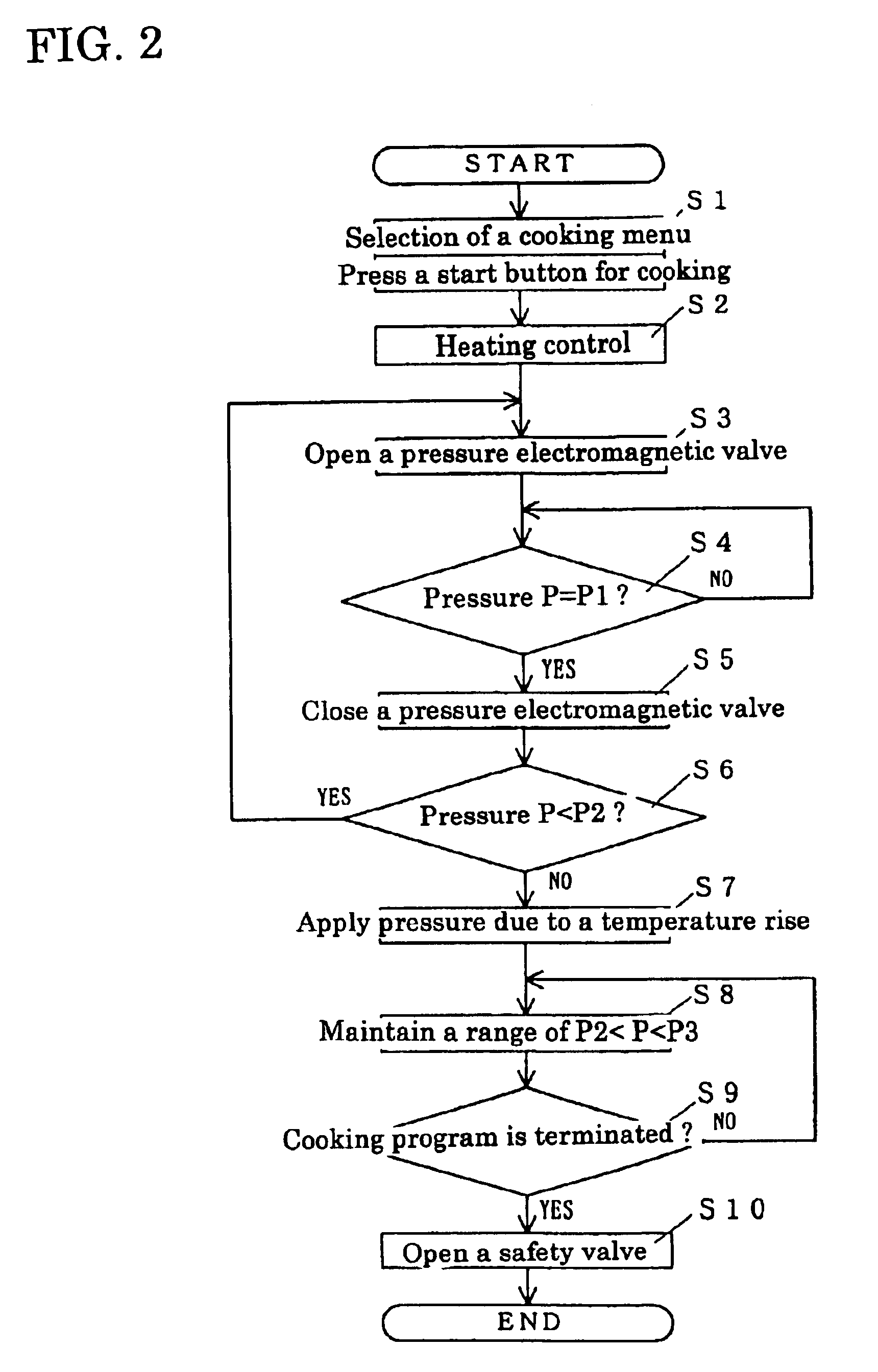
[0028]In this embodiment, the time for opening a the pressure electromagnetic valve 14 (that is, a pressure timer) is previously set in a controller 18 according to a cooking menu. For example, a pressure timer for one piece of fried chicken is set for 80 seconds, and as the number of the fried chicken pieces increases by one piece, the pressure time is set to be shortened by 10 seconds. As shown in FIG. 3, a certain cooking menu is selected and a start button is pressed at S1. Then a burner 4 is ignited for starting heating control at S2. The pressure electromagnetic valve 14 is...

third embodiment

[0032]In the embodiment described below, the supply of carbon dioxide is selected according to cooking oil temperature obtained from the temperature sensor 11. As shown in FIG. 4, a certain cooking menu is selected and a start button is pressed at S1. Then a burner 4 is ignited for starting heating control at S2, and at the same time, a temperature monitoring timer set for a predetermined time starts counting. When the temperature monitoring timer is up at S3, it is determined whether or not a cooking oil temperature T reaches a predetermined temperature T1 at S4. It should be noted that the temperature T may be determined based on a rise gradient of temperature within a predetermined time.

[0033]If the cooking oil temperature reaches the predetermined temperature T1, it is determined that the amount of food is small, and the pressure electromagnetic valve 14 is opened at S5. While the valve is open, carbon dioxide is supplied into the cooking container 3 until a predetermined openin...


PUM


Abstract

A pressure fryer is provided including a cooking container having a pressure vent which is connected to a high pressure cylinder filled with carbon dioxide. An electromagnetic valve and a check valve are provided on the connecting tube between the pressure vent and the high pressure cylinder. A lid includes a safety valve and a pressure sensor. A controller opens and closes the safety valve and the pressure for the electromagnetic valve for supplying carbon dioxide into the cooking container based on the pressure therein which is obtained from the pressure sensor, such that the pressure in the cooking container can be maintained within a predetermined value.

Description

BACKGROUND OF THE INVENTION[0001]This application claims the benefit of Japanese Patent Application Number 2003-8708 filed Jan. 16, 2003, the entirety of which is incorporated by reference.[0002]1. Field of the Invention[0003]This invention relates to a pressure fryer including a cooking container for containing cooking oil that is capable of being hermetically sealed and a heating means for heating the cooking container so as to cook foods, such as fried chicken or fried potatoes, with pressure.[0004]2. Description of the Related Art[0005]Conventionally, a fryer include a cooking container for containing cooking oil, a heating means, such as a burner, for heating the cooking container, and a controller serving as a control means for controlling the operation of the heating means. Further, the operation of the heating means is controlled according to a cooking program stored by the controller, which enables the fryer to cook foods (see, for example, Japanese Patent Unexamined Public...

Claims


Application Information

Patent Timeline
Patent Type & Authority Patents(United States)
IPC IPC(8): A47J27/08A47J37/12
CPCA47J27/0817Y10S210/08
Inventor KOBAYASHI, TOSHIHIRO
Owner PALOMA
Why Eureka
Try Eureka