Self-deploying funnel

a funnel and self-deploying technology, applied in the field of funnels, can solve the problems of dirty clothes, dirt, grime or other debris in the crankcase, and the messy task of filling the crankcase of an internal combustion engine with oil as part of the oil change procedur

Inactive Publication Date: 2005-08-30
RINALDI MARK
View PDF4 Cites 34 Cited by
  • Summary
  • Abstract
  • Description
  • Claims
  • Application Information

AI Technical Summary

Benefits of technology

[0028]An important advantage of this invention is that it provides a funnel that remains clean when it is stored.
[0029]Another important advantage of the novel funnel is that it need not be held in one hand during an oil-changing procedure.
[0030]Another advantage is that the novel funnel occupies a small space when in storage yet deploys into its full size in the absence of being handled directly by the funnel user.
[0031]Still another advantage is that the novel funnel is never handled directly by a user during deployment, use, and storage, thereby keeping the user's hands and clothes clean throughout the entire oil-changing process.
[0032]Yet another advantage is that the funnel is made of a self-biasing material, thereby avoiding a need for a funnel and a separate bias means for deploying the funnel.

Problems solved by technology

Still, re-filling the crankcase of an internal combustion engine with oil as a part of the oil change procedure is a messy task if the right equipment is not used.
This widely-practiced, well-known technique usually results in spilled oil, introduction of dirt, grime, or other debris into the crankcase, dirty clothes, and the like.
Dirt, grime, and other debris can enter into the crankcase, shortening engine life, because such materials usually accumulate around the oil fill cap and are easily knocked into the oil fill orifice by the hand-held funnel.
Oil spills often occur during such procedure, especially if the funnel is used in low light or other less-than-ideal conditions.
If the engine is hot at the time a spill is made, a fire causing human injury can occur.
Moreover, the engine can be rendered inoperable if such a fire damages the electrical wiring, the vacuum lines, the fuel lines, or the like.
This results in the accumulation of dirt and grime to the extent that the funnel is unacceptably fouled by the time it is re-used.
Thus, they should be disposed of as hazardous waste but most users place them in regular trash receptacles, to the detriment of the environment.

Method used


Image

  • Self-deploying funnel
  • Self-deploying funnel
  • Self-deploying funnel

Examples


first embodiment

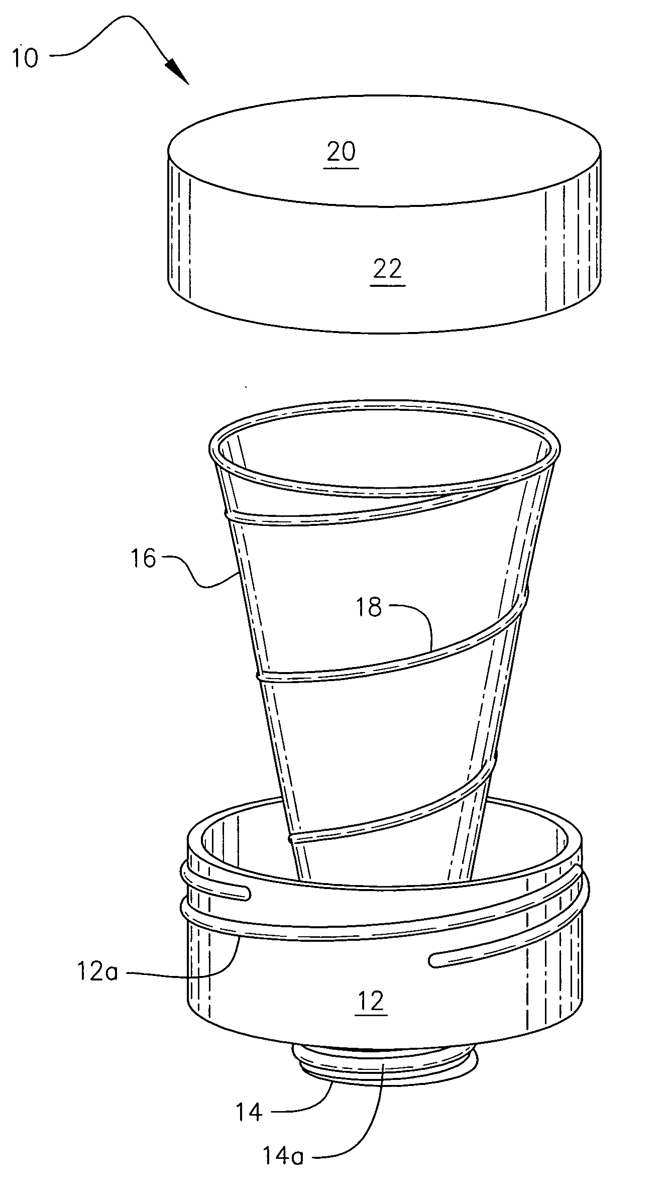
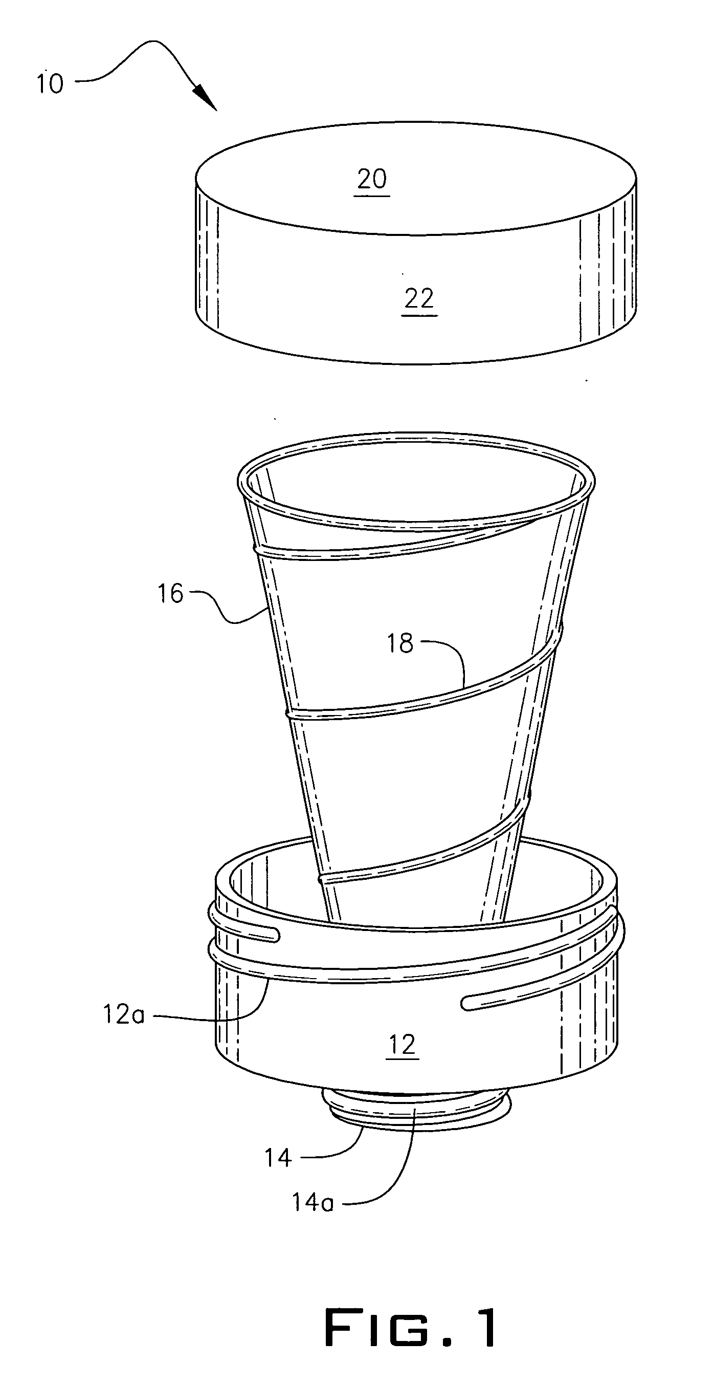
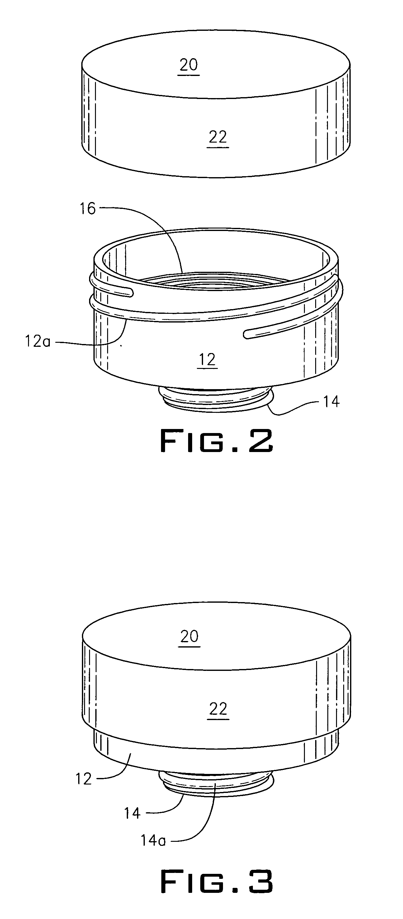
[0047]In FIGS. 1–3, external helical threads 12a are formed about the circumference of base 12 and mating internal threads, not depicted, are formed in an interior surface of sidewall 22. This enables cap 20 to screw-threadedly engage base 12 in the manner depicted in FIG. 3. When in its FIG. 3 configuration, funnel 16 is in a collapsed, or telescoped configuration. Accordingly, when so contracted it occupies much less space than when in its fully deployed configuration as depicted in FIG. 1.

[0048]Significantly, when cap 20 is unscrewed from base 12, the user need not grasp funnel 16 to cause its deployment. Instead, helical and conical spring 18 is loaded when cap 20 is secured to base 12 and said spring 18 unloads when said cap is removed, thereby deploying funnel 16. Therefore it is said that funnel 16 is a self-deploying or self-extracting funnel. The user firmly grasps cap 20 and sidewall 22 as said cap is unscrewed so that said user may allow deployment of funnel 16 at a reaso...

second embodiment

[0057]The first alternative method for such releasable securement is depicted in FIGS. 4–6. Known as a bayonet mount, this locking means includes a couple of “L”-shaped slots, collectively denoted 24, formed in base 12 in circumferentially spaced apart relation to one another. Each slot 24 includes a vertical section 24a, a circumferentially-extending section 24b, and a vertical, truncate section 24c. A protuberance, not shown, is formed on the interior wall of sidewall 22 of cap 20 and is sized to slidingly engage all three sections of “L”-shaped slot 24.

[0058]More particularly, cap 20 is used to compress funnel 16 as in the first embodiment, and the undepicted protuberance is inserted into section 24a until it bottoms out. Cap 20 is then rotated about its axis of rotation so that the undepicted protuberance enters into slot section 24b and reaches the end thereof. Cap 20 is then released and the inherent bias of funnel 16 drives the undepicted protuberance to the top end of slot s...

third embodiment

[0061]a means for releasably securing cap 20 to base 12 is depicted in FIGS. 7–9. A pair of catches, collectively denoted 26, is formed on an exterior sidewall of base 12 in diametrically opposed relation to one another. They may also be circumferentially spaced apart from one another in a relationship other than such diametric opposition. Only one of said catches 26 is fully visible in said Figs.

[0062]A pair of latches, denoted 28, that respectively mate with said catches 26, is formed on an exterior side wall of cap 20 in diametrically opposed relation to one another and in mating relation to the catches. Only one of said catches is visible in these views. Each latch 26 is apertured as at 30 to receive its associated catch 28. Each latch 26 is also slightly pivotable about a transverse axis mid-length of each latch so that each latch can be disengaged from its associated catch by a squeezing action applied simultaneously to the opposed latches as indicated by converging arrows 32a...


PUM

PropertyMeasurementUnit
diameteraaaaaaaaaa
mid-lengthaaaaaaaaaa
sizeaaaaaaaaaa

Abstract

A funnel assembly includes a collapsible funnel mounted to a base. The funnel is formed by consecutive windings of spring steel wire. Each winding has a reduced diameter so that the windings collectively form a funnel having a conical shape and an inherent bias. The funnel is confined into a relatively small storage space and the funnel is compressed when a cap releasably engages the base. Upon disengaging the cap from the base, the bias unloads and fully deploys the funnel. A downspout depends from the base and engages the fill spout of an oil crankcase so that the funnel assembly is mounted to the fill spout. A user therefore does not hold the funnel assembly while pouring oil from a can into the deployed funnel. By holding the base in one hand and the cap in the other, a user may deploy the funnel and return it to storage without touching the funnel.

Description

CROSS-REFERENCE TO RELATED APPLICATIONS[0001]This disclosure is a continuation-in-part of a provisional application filed by the present inventor on May 12, 2004, application No. 60 / 570,280, entitled “Self-Extracting Funnel.”BACKGROUND OF THE INVENTION[0002]1. Field of the Invention[0003]This invention relates, generally, to funnels of the type used in changing oil. More particularly, it relates to a funnel having a small, compact configuration when in storage and a larger, full size when fully deployed in an operative configuration.[0004]2. Description of the Prior Art[0005]Most manufacturers now recommend an oil change every five thousand miles instead of the previous recommendation of every three thousand miles. Still, re-filling the crankcase of an internal combustion engine with oil as a part of the oil change procedure is a messy task if the right equipment is not used. Most do-it-yourself methods require that an oil can be held in one hand and a funnel in the other during the...

Claims


Application Information

Patent Timeline
Patent Type & Authority Patents(United States)
IPC IPC(8): B65B1/04B65B39/02B67C11/02F16N37/00
CPCB65B39/02B67C11/02B67C2011/027F16N2037/006
Inventor RINALDI, MARK
Owner RINALDI MARK
Why Eureka
Try Eureka