Metal single layer abrasive cutting tool having a contoured cutting surface

a single-layer abrasive and cutting tool technology, applied in the direction of manufacturing tools, gear teeth, manufacturing apparatus, etc., can solve the problems of high penetration rate and high cutting rate, and the penetration rate of the tool quickly drops to zero

Inactive Publication Date: 2005-08-30
SAINT GOBAIN ABRASIVES TECH CO
View PDF41 Cites 36 Cited by
  • Summary
  • Abstract
  • Description
  • Claims
  • Application Information

AI Technical Summary

Benefits of technology

[0017]wherein the constant force is sufficient to cut the workpiece, the strength of the bond is sufficient to resist peeling, the predetermined wear resistance of the grains is such that the grains of the first uppermost cutting level fracture under application of the constant force, and the wear resistance of the teeth are such that the portion of the tooth associated with the first uppermost-cutting level wears at about the same rate as the grains of the first uppermost cutting level fracture, thereby causing essentially simultaneous removal of the grains of the first uppermost cutting level from their bond and the portion of the tooth associated with the first uppermost cutting level, andthereby exposing the grains of the second uppermost cutting level to the workpiece.

Problems solved by technology

This condition produces high penetration rates and high cutting rates.
However, since the SL tool has only a single layer of abrasive, it can no longer effectively cut once that layer is dulled during operation.
However, since the abrasive grit is embedded in a metal matrix, both the metal matrix and the abrasive grit are exposed on the tool periphery.
However, the large size, high concentration and low toughness of the grains are such that these uppermost grains quickly dull when cutting hard surfaces such as masonry, and the penetration rate of the tool quickly falls to zero.
However, the weak mechanical nature of the electroplate bond results in the lower levels of grains being peeled from the tooth.
Accordingly, the usefulness of the tool is limited to the usefulness of the uppermost layer of grains.

Method used


Image

  • Metal single layer abrasive cutting tool having a contoured cutting surface
  • Metal single layer abrasive cutting tool having a contoured cutting surface
  • Metal single layer abrasive cutting tool having a contoured cutting surface

Examples


example i

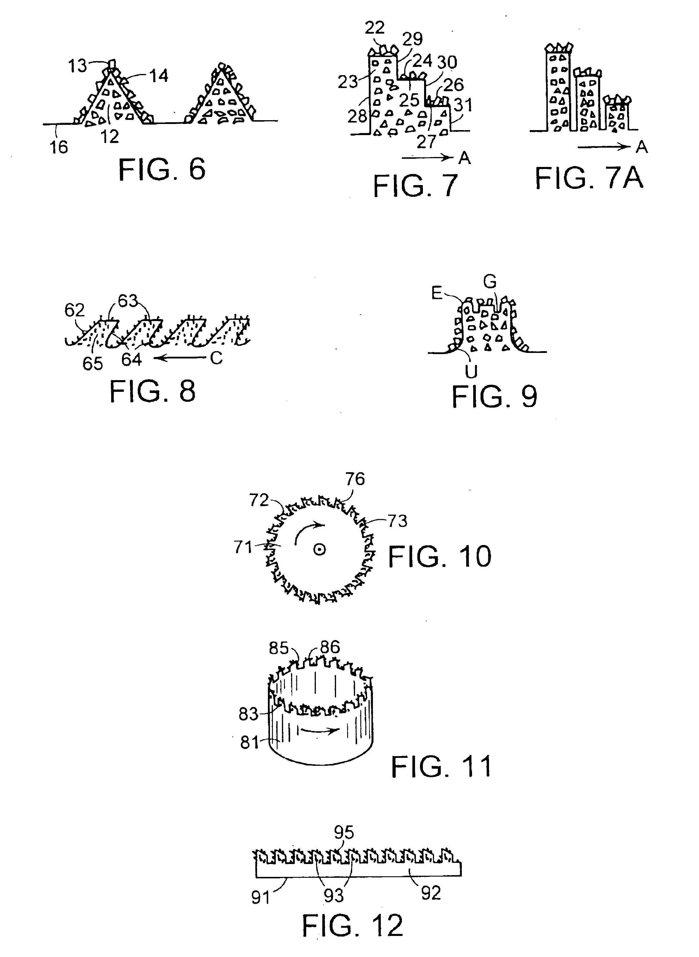
[0083]In this embodiment, core drills of the present invention were made using 66 mm diameter outlet bits having a 2 mm wall thickness and made of 1020 steel having a 38-42 Ra hardness. The contour of the cutting surface was substantially similar to that shown in FIG. 9.

[0084]The crown of the bit was contoured by turning a 1 mm radius onto the leading edge of the steel substrate and then milling nine 0.050 inch wide slots spaced equally around the periphery. This procedure produced nine 0.402 inch wide, 0.200 high teeth. Two equally spaced radial grooves (0.0625 inches wide, 0.0625 inches deep) were then ground into the face of each tooth. A 0.035 inch layer of bronze titanium was then applied to the teeth and a layer of 35 / 40 SDA 100+ diamond (about 450 mg) was applied to the braze surface and the resulting assembly was placed in a vacuum furnace for conventional braze curing.

[0085]Bits made in accordance with this example were used to hand drill heavy weight concrete HCB blocks. A...

example ii

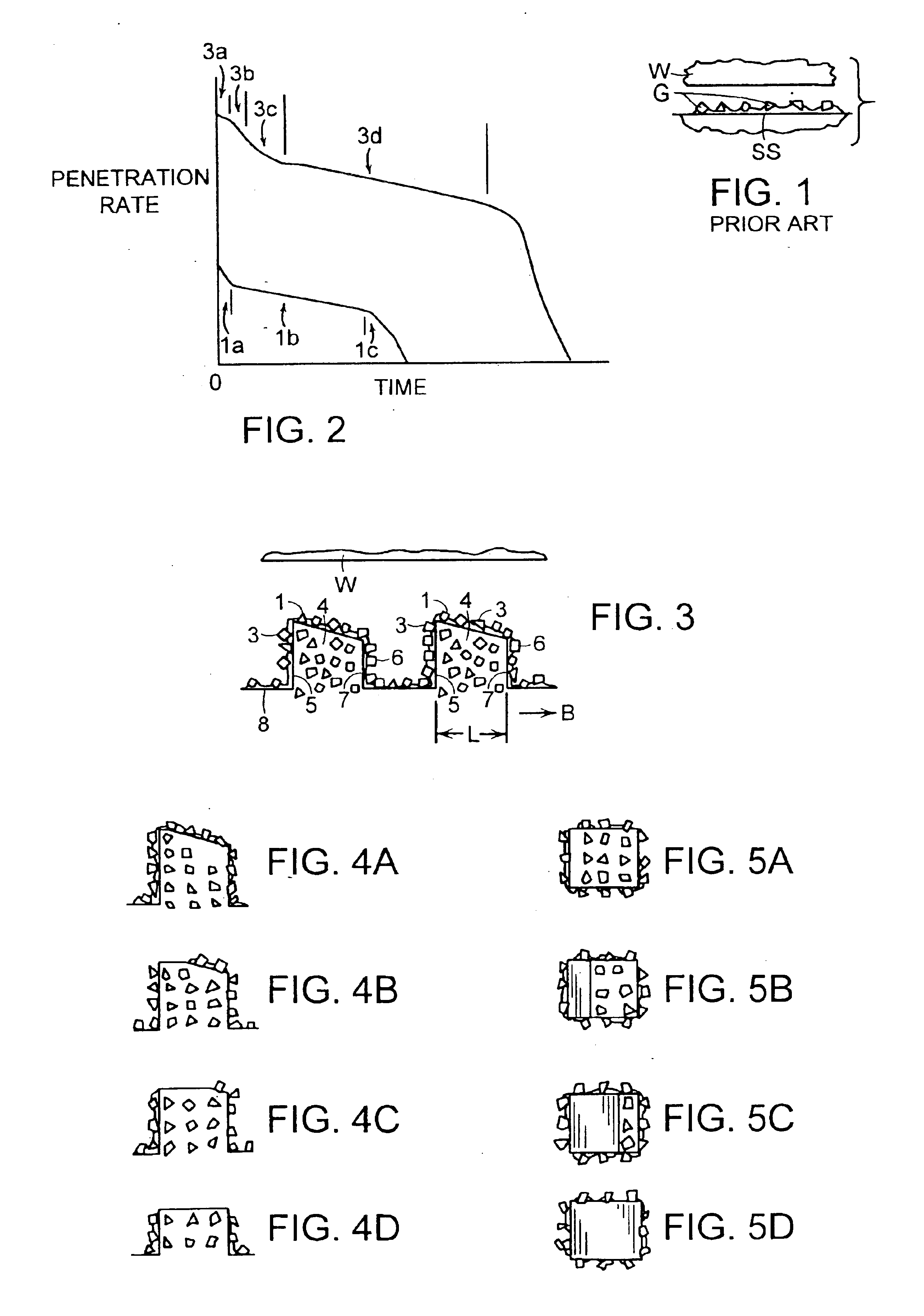
[0086]In this embodiment, tools of the present invention were made using 66 mm diameter outlet bits having a 2 mm wall thickness and made of 1020 steel having a 38-42 Ra hardness. The contour of the cutting surface was substantially similar to that shown in FIG. 8.

[0087]A single layer of abrasive grain consisting essentially of 0.5 g of 35\40 mesh SDA 100+ diamond and bronze-titanium braze was applied to the contour of each bit.

[0088]These bits were use to drill holes in HCB blocks. Initial penetration rates were about 3-4 inches a minute. Although the diamond on the leading edge of the contour was worn away after only a few holes, the bits continued to drill over four meters of concrete block. When the tests were suspended after each bit drilled 80 holes, the bits were still drilling at an acceptable rate of about 1.5-2 inches (3.8-5 cm) per minute. Drilling power varied between about 350 and 550 watts over the course of the test, while specific energy varied between about 0.30 and...

example iii

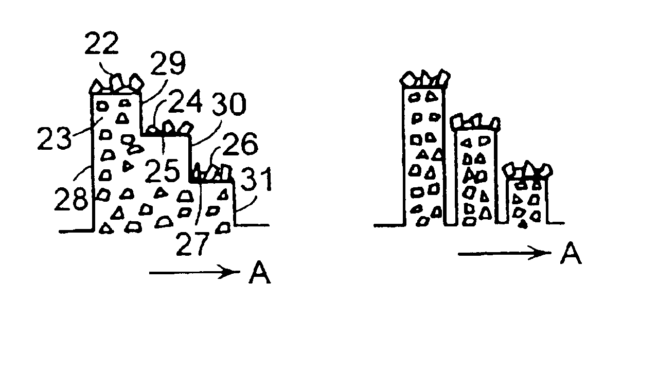
[0089]This test examined the behavior of a hole saw having a reversed tooth orientation. The tooth configuration in this case was similar to that of Example II, except that the angle of orientation was reversed so that the descending portion of the tooth was the leading edge, thereby producing positive rake. These tools were tested under conditions substantially similar to those of Example I. After drilling only 5 cm, the teeth were so worn that only 20% of the height of the tooth remained. (In contrast, this level of wear was found in the teeth of Example II only after a full 400 cm of drilling.) This tool drilled for 396 cm before the penetration rate fell below 2.5 cm / min and had an average penetration rate of 5.4 cm / min. Accordingly, the tool having teeth oriented for a negative rake produces superior results.

[0090]The results of the above tests are summarized in Table I.

[0091]

TABLE ITESTDistance Drilled (cm)Speed (cm / min)C. E. I100—C. E. II4005.3C. E. III003—E. I490-5605E. II98...


PUM

PropertyMeasurementUnit
angleaaaaaaaaaa
angleaaaaaaaaaa
angleaaaaaaaaaa

Abstract

This invention relates to an abrasive cutting tool comprising:i) a substrate surface having a plurality of teeth extending therefrom, andii) a single layer of abrasive grains chemically bonded to at least a portion of each tooth to define a plurality of cutting levels parallel to the substrate surface, the cutting levels comprising a first uppermost cutting level and a second uppermost cutting level, the grains having a predetermined concentration, size and toughness, whereby the abrasive cutting tool has a cutting surface with a negative angle of inclination with respect to an intended direction of cutting.

Description

[0001]This application is a divisional application claiming priority in U.S. Ser. No. 08 / 892,836, filed Jul. 15, 1997, now U.S. Pat. No. 6,817,936, and U.S. Ser. No. 08 / 616,538, filed Mar. 15, 1996, now abandoned.BACKGROUND OF THE INVENTION[0002]Superhard abrasive cutting tools fitted with saw blades, core bits and cutting wheels for use in construction applications are typically classified as either metal matrix bonded (MB) or as metal single layer (SL). The SL cutting tool has a single layer of abrasive grain (or “grit”) bonded to a smooth metal substrate by a minimum of bond material so that the abrasive grit is essentially exposed on the cutting surface of the tool. When the cutting surface is presented to the workpiece to be cut, substantially only the abrasive grit contacts the workpiece. Since a substantial portion of the load of the tool is carried by the abrasive grit, the load on each cutting point of the grit is very high. This condition produces high penetration rates an...

Claims


Application Information

Patent Timeline
Patent Type & Authority Patents(United States)
IPC IPC(8): B23D61/00B23D61/18B28D1/04B28D1/12B28D1/02
CPCB23D61/18B28D1/12B28D1/041
Inventor SKEEM, MARCUS R.BULJAN, SERGEJ-TOMISLAVKRAMP, JEAN
Owner SAINT GOBAIN ABRASIVES TECH CO
Why Eureka
Try Eureka