Silicon carbide gate transistor

Inactive Publication Date: 2005-08-30
MICRON TECH INC
View PDF128 Cites 27 Cited by
  • Summary
  • Abstract
  • Description
  • Claims
  • Application Information

AI Technical Summary

Benefits of technology

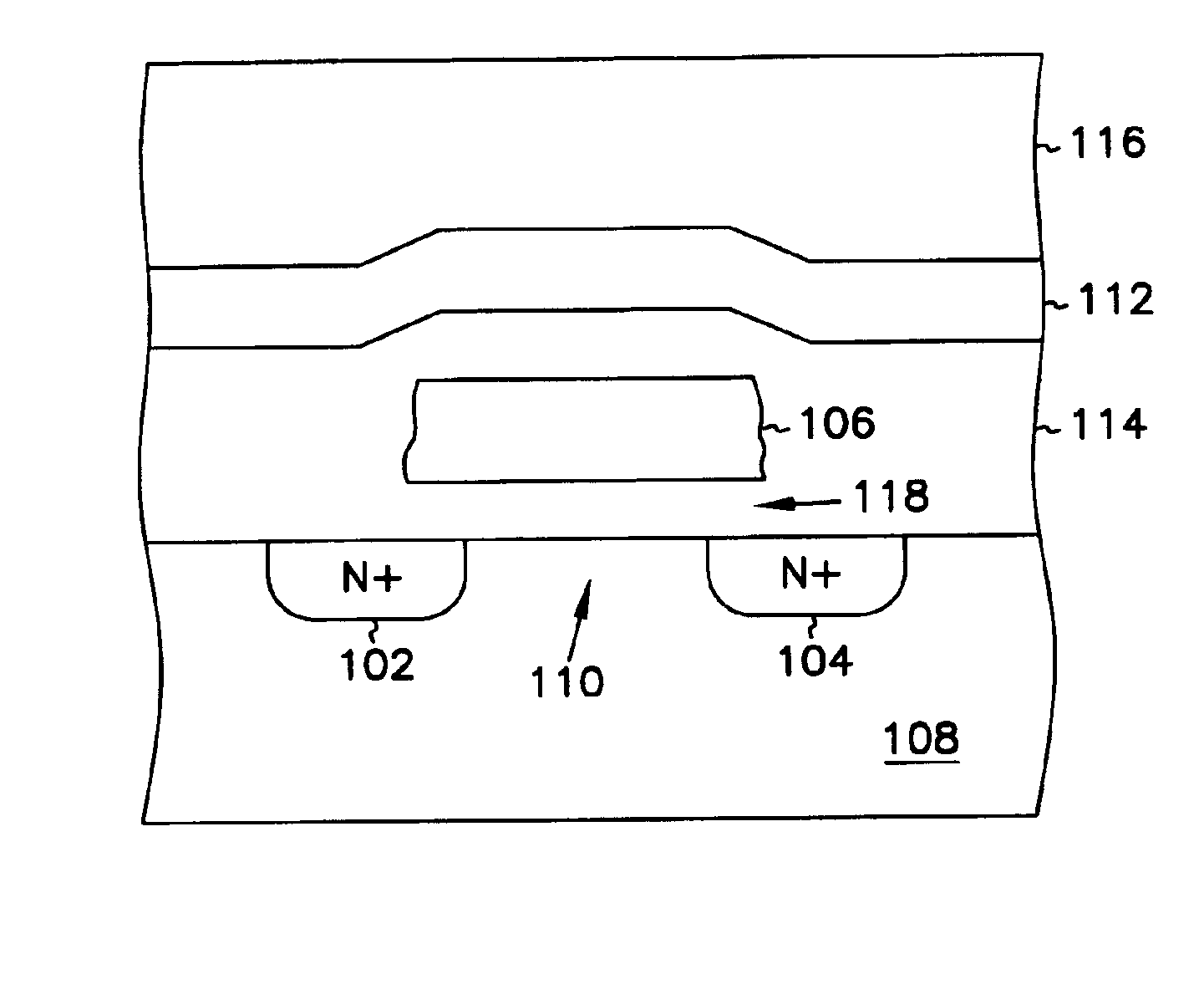
[0010]The invention provides numerous advantages. For example, the SiC gate FET provides lower VT magnitudes, allowing integrated circuit operation at lower power supply voltages. The lower power supply voltage, in turn, provides advantages including lower power consumption and ease in downward scaling of transistor dimensions without unacceptably increasing electric fields. The lower VT magnitudes also enable higher switching speeds and improved performance. The SiC gate FET also provides lower VT ma

Problems solved by technology

For example, for p-channel FETs fabricated by a typical CMOS process, these and other material properties result in a large turn-on threshold voltage (VT) magnitude.
One drawback of polysilicon gate FETs is that the VT magnitude adjustment by ion-implantation is particularly difficult to carry out in semiconductor-on-insulator (SOI) and other thin film transistor technology.
The semiconductor layer may be only 1000 Å thick, making it difficult to obtain a

Method used


Image

  • Silicon carbide gate transistor
  • Silicon carbide gate transistor
  • Silicon carbide gate transistor

Examples


Embodiment Construction

[0017]In the following detailed description of the preferred embodiment, reference is made to the accompanying drawings which form a part hereof, and in which is shown, by way of illustration, a specific embodiment in which the invention may be practiced. In the drawings, like numerals describe substantially similar components throughout the several views. This embodiment is described in sufficient detail to enable those skilled in the art to practice the invention. Other embodiments may be utilized and structural and electrical changes may be made without departing from the scope of the present invention. The terms wafer and substrate used in the following description include any semiconductor-based structure having an exposed surface with which to form the integrated circuit structure of the invention. Wafer and substrate are used interchangeably to refer to semiconductor structures during processing, and may include other layers that have been fabricated thereupon. Both wafer and...


PUM


Abstract

A field-effect transistor (FET) device and method of fabrication uses an electrically interconnected polycrystalline or microcrystalline silicon carbide (SiC) gate having a lower electron affinity and higher work function than a polysilicon gate FET. The smaller threshold voltage magnitude of the SiC gate FET allows reduced power supply voltages (lowering power consumption and facilitating downward scaling of transistor dimensions), and enables higher switching speeds and improved performance. The smaller threshold voltage magnitudes are obtained without ion-implantation, which is particularly useful for SOI and thin film transistor devices. Threshold voltage magnitudes are stable in spite of subsequent thermal processing steps. N-channel threshold voltages are optimized for enhancement mode.

Description

FIELD OF THE INVENTION[0001]The present invention relates generally to integrated circuits, and particularly to a silicon carbide gate field-effect transistor and complementary metal-oxide-semiconductor (CMOS) compatible method of fabrication.BACKGROUND OF THE INVENTION[0002]Field-effect transistors (FETs) are typically produced using a standard complementary metal-oxide-semiconductor (CMOS) integrated circuit fabrication process. As is well known in the art, such a process allows a high degree of integration such that a high circuit density can be obtained with relatively few well-established masking and processing steps. A standard CMOS process is typically used to fabricate FETs that each have a gate electrode that is composed of n-type conductively doped polycrystalline silicon (polysilicon) material.[0003]The intrinsic properties of the polysilicon gate material affect operating characteristics of the FET that is fabricated using a standard CMOS process. Silicon (monocrystallin...

Claims


Application Information

Patent Timeline
IPC IPC(8): H01L21/28H01L21/02H01L21/70H01L29/78H01L21/8238H01L29/66
CPCH01L21/28255H01L21/823828H01L29/78Y10S438/931
Inventor FORBES, LEONARDAHN, KIE Y.
Owner MICRON TECH INC
Why Eureka
Try Eureka