Microphone for a listening device having a reduced humidity coefficient

a technology of humidity coefficient and microphone, applied in the direction of microphone structure association, geological measurement, transducer type, etc., can solve the problem of coefficient affecting the sensitivity of the microphone, and achieve the effect of minimizing the undesirable effects

Inactive Publication Date: 2005-08-30
SONION NEDERLAND
View PDF31 Cites 35 Cited by
  • Summary
  • Abstract
  • Description
  • Claims
  • Application Information

AI Technical Summary

Benefits of technology

[0010]The diaphragm moves toward the backplate in response to an increasing relative humidity. Due to the differing coefficients of hygroscopic expansion, the backplate also moves away from the diaphragm in response to an increasing relative humidity. Thus, the first layer and the second layer can be selected to minimize the undesirable effects that occur when the diaphragm is subjected to high humidity conditions.

Problems solved by technology

Thus, prior art microphones have a humidity coefficient that affects the sensitivity of the microphone.

Method used


Image

  • Microphone for a listening device having a reduced humidity coefficient
  • Microphone for a listening device having a reduced humidity coefficient
  • Microphone for a listening device having a reduced humidity coefficient

Examples


Embodiment Construction

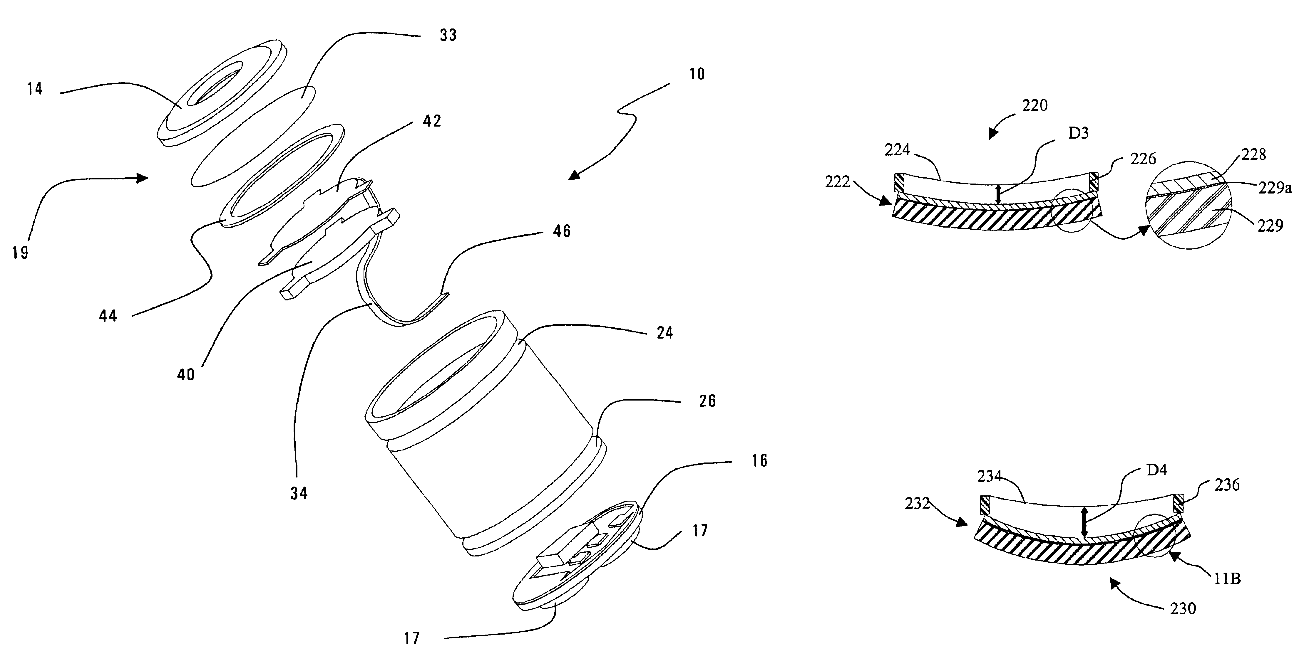
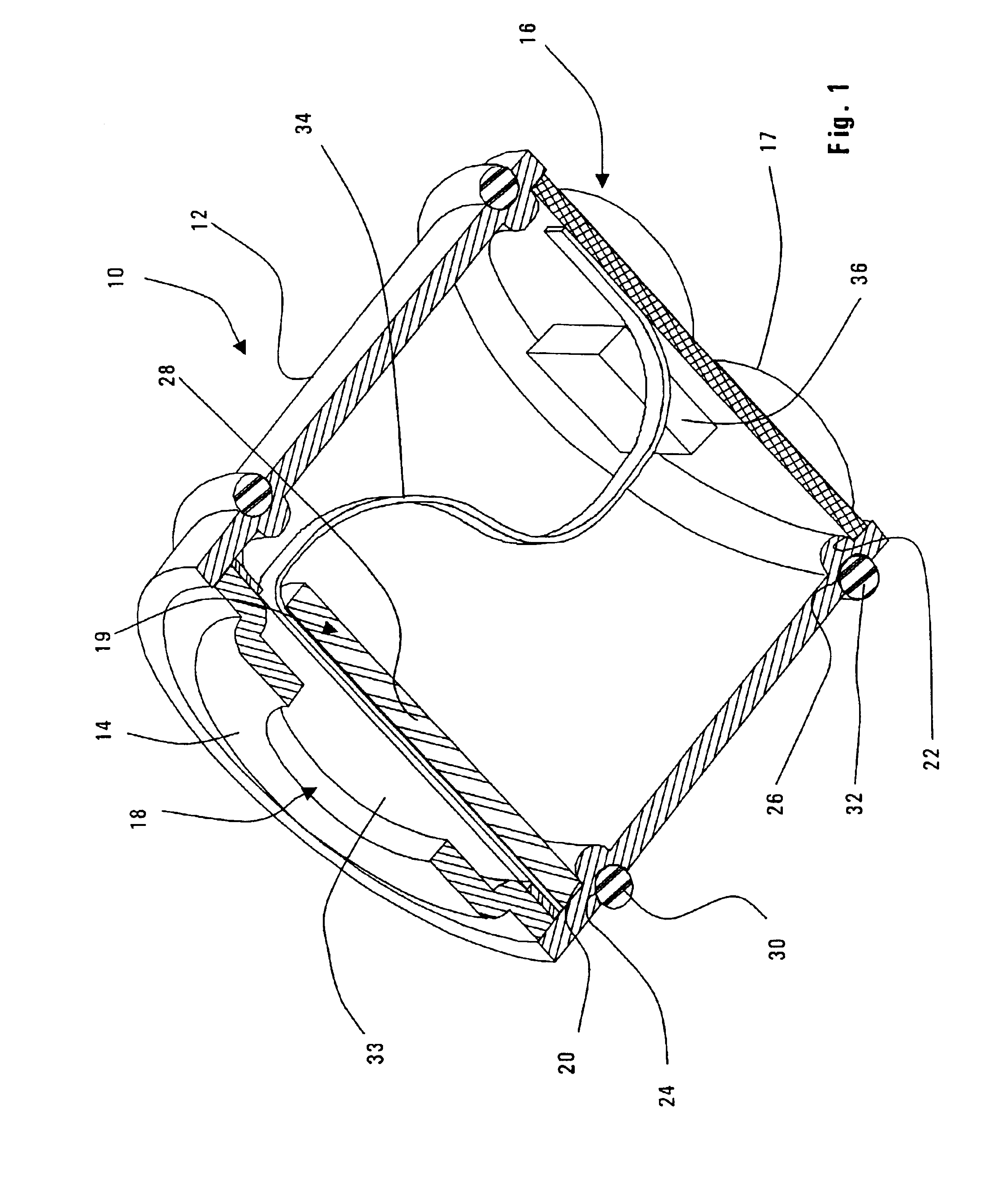
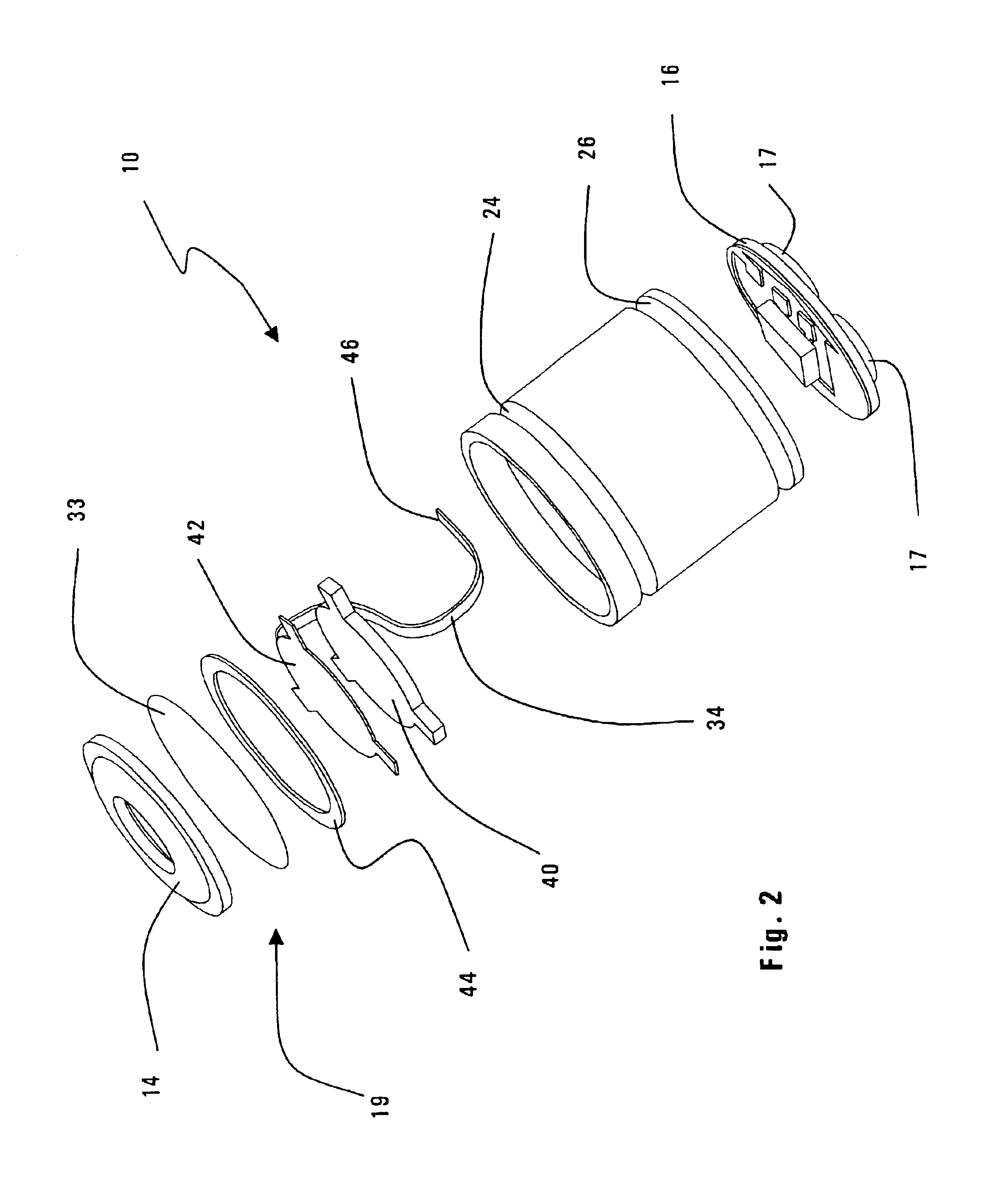
[0028]Referring to FIG. 1, a microphone 10 according to the present invention includes a housing 12 having a cover assembly 14 at its upper end and a printed circuit board (PCB) 16 at its lower end. While the housing 12 has a cylindrical shape, it can also be a polygonal shape, such as one that approximates a cylinder. In one preferred embodiment, the axial length of the microphone 10 is about 2.5 mm, although the length may vary depending on the output response required from the microphone 10.

[0029]The PCB 16 includes three terminals 17 (see FIG. 2) that provide a ground, an input power supply, and an output for the processed electrical signal corresponding to a sound that is transduced by the microphone 10. The sound enters the sound port 18 of the cover assembly 14 and encounters an electret assembly 19 located a short distance below the sound port 18. It is the electret assembly 19 that transduces the sound into the electrical signal.

[0030]The microphone 10 includes an upper rid...


PUM


Abstract

A microphone is constructed to be more tolerant to a wide range of relative humidity conditions without adversely affecting the performance of the microphone. The microphone includes a housing with a sound port for receiving sound and an electret assembly for converting the sound into an output signal. The electret assembly includes a diaphragm and a backplate. The backplate is made of at least two layers, usually polymeric layers. The first layer of material has a first hygroscopic coefficient and a second layer of material has a second hygroscopic coefficient. The first and second layers cause the backplate to bend in response to higher humidity conditions, thereby minimizing the adverse effects on microphone performance caused by characteristic changes in the diaphragm at the higher humidity conditions.

Description

RELATED APPLICATIONS[0001]This application is a continuation-in-part of U.S. patent application Ser. No. 10 / 124,683, filed Apr. 17, 2002, which claims the benefit of priority of U.S. Provisional Patent Application Nos. 60 / 301,736, filed Jun. 28, 2001 now abandoned, and 60 / 284,741, filed Apr. 18, 2001 now abandoned.FIELD OF THE INVENTION[0002]The present invention relates generally to electroacoustic transducers and, in particular, to a microphone or listening device with an improved performance over a wide range of relative humidity.BACKGROUND OF THE INVENTION[0003]Miniature microphones, such as those used in hearing aids, convert acoustical sound waves into an electrical signal which is processed (e.g., amplified) and sent to a receiver of the hearing aid. The receiver then converts the processed signal to acoustical sound waves that are broadcast towards the eardrum.[0004]In one typical microphone, a moveable diaphragm and a rigid backplate, often collectively referred to as an el...

Claims


Application Information

Patent Timeline
Patent Type & Authority Patents(United States)
IPC IPC(8): H04R19/00H04R1/04H04R19/01H04R25/00
CPCH04R1/04H04R19/016H04R25/00
Inventor DE ROO, DION I.LAFORT, ADRIANUS M.DE NOOIJ, MICHELMOGELIN, RAYMOND
Owner SONION NEDERLAND
Why Eureka
Try Eureka