Traction drive

a technology of traction drive and traction control, which is applied in the direction of motor/generator/converter stopper, dynamo-electric converter control, stopping arrangement, etc., can solve the problems of complex system prone to malfunction, high cost and frequent maintenance, and flat spots on the wheel sets, so as to reduce the cost of maintenance and reduce the mass , the effect of eliminating mechanical brakes

Inactive Publication Date: 2005-09-06
SIEMENS AG
View PDF10 Cites 21 Cited by
  • Summary
  • Abstract
  • Description
  • Claims
  • Application Information

AI Technical Summary

Benefits of technology

[0012]This approach can entirely eliminate mechanical brakes on a traction wheel of a rail car and the costs associated with maintaining a mechanical brake. Since a mechanical brake is the longer required, a traction wheel is not only less costly, but also has a lower mass.
[0013]Advantages embodiments of the traction drive may include one or more of the following features. With a synchronous motor, the brake resistors can be ohmic resistors having a current- or ...

Problems solved by technology

The mechanical brakes disadvantageously represent a complex system prone to malfunction, that can be quite expensive and require frequent maintenance.
Moreove...

Method used


Image

  • Traction drive
  • Traction drive
  • Traction drive

Examples


Embodiment Construction

[0018]Throughout all the Figures, same or corresponding elements are generally indicated by same reference numerals. These depicted embodiments are to be understood as illustrative of the invention and not as limiting in any way. It should also be understood that the drawings are not necessarily to scale and that the embodiments are sometimes illustrated by graphic symbols, phantom lines, diagrammatic representations and fragmentary views. In certain instances, details which are not necessary for an understanding of the present invention or which render other details difficult to perceive may have been omitted.

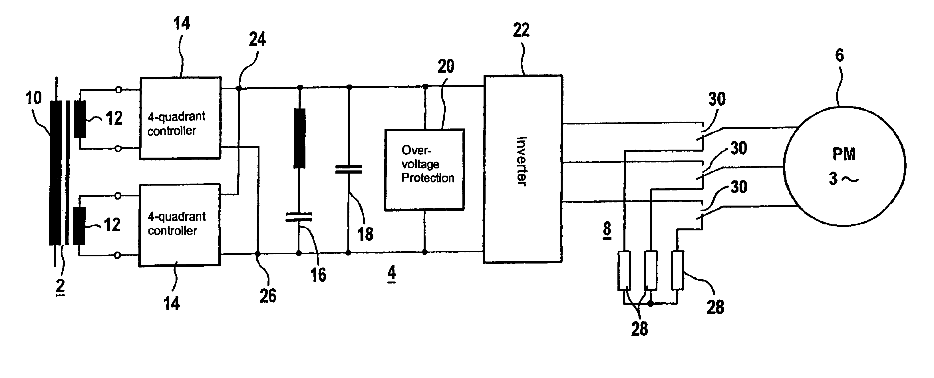
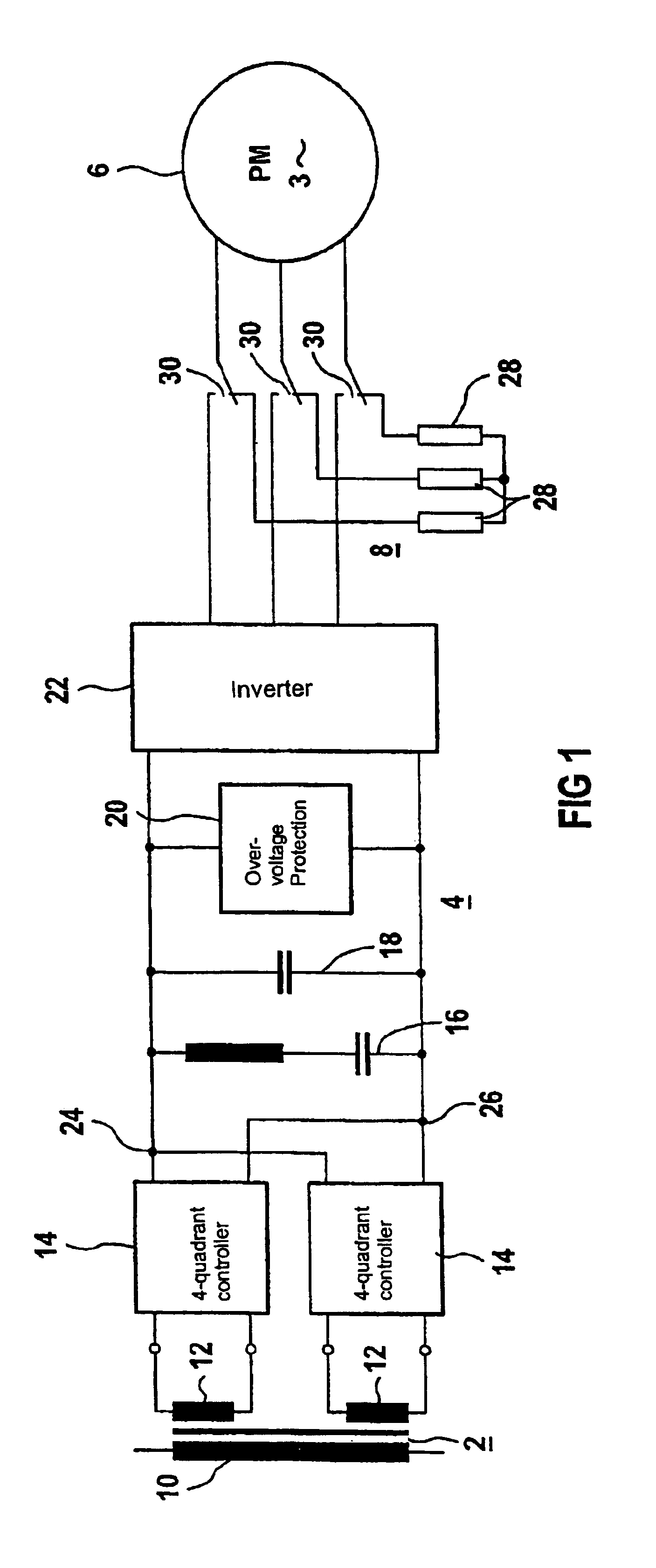
[0019]Turning now to the drawing, and in particular to FIG. 1, there is shown in more detail a circuit diagram of a traction drive for a vehicle powered by alternating current, also referred to as AC-vehicle. The traction drive includes a traction transformer 2, a traction converter 4, a permanent-excited synchronous motor 6, and a brake system 8. The exemplary traction transf...


PUM


Abstract

A traction drive, in particular for rail cars, includes a permanent-excited synchronous motor, a traction converter with a pulsed inverter for powering the motor, and ohmic brake resistors. Cross-over switches are connected with a corresponding input terminal of the motor and can switch the input terminal between a corresponding output terminal of the pulsed inverter (for travel) and a terminal of a corresponding brake resistor (for braking). The brake resistors are electrically connected in a star configuration. The traction drive can operate with different supply voltages. There is no longer a need for a mechanical brake, and flat spots on the wheels can be prevented.

Description

CROSS-REFERENCES TO RELATED APPLICATIONS[0001]This application is a continuation of prior filed copending PCT International application no. PCT / DE02 / 04380, filed Nov. 28, 2002, which designated the United States and on which priority is claimed under 35 U.S.C. §120, the disclosure of which is hereby incorporated by reference.[0002]This application claims the priority of German Patent Application, Serial No. 101 60 612.5, filed Dec. 11, 2001, pursuant to 35 U.S.C. 119(a)-(d), the disclosure of which is incorporated herein by reference.BACKGROUND OF THE INVENTION[0003]The present invention relates to a traction drive with a converter and a permanent-excited synchronous motor, wherein the converter includes a machine-side pulsed inverter.[0004]Conventional traction wheels of rail cars include asynchronous drive motors that are powered by traction drives with pulsed inverters. These traction drives can also be operated as a generator brake in travel and braking mode. A wheel set must ha...

Claims


Application Information

Patent Timeline
IPC IPC(8): B60L7/00B60L7/02H02P6/00H02P6/24
CPCB60L7/06H02P6/24B60L2220/14Y02T10/642B60L2200/26Y02T10/64
Inventor JOCKEL, ANDREAS
Owner SIEMENS AG
Why Eureka
Try Eureka