
Emergency vehicle traffic signal preemption system

a technology for emergency vehicles and traffic signals, applied in vehicle position/course/altitude control, process and machine control, instruments, etc., can solve the problems of not providing real-time monitoring of intersection phases, all of these known systems have severe operational limitations, and operators do not get the feedback desired

Inactive Publication Date: 2005-09-06
CALIFORNIA INST OF TECH
View PDF7 Cites 88 Cited by
  • Summary
  • Abstract
  • Description
  • Claims
  • Application Information

AI Technical Summary

Benefits of technology

[0016]The purpose of the present invention is to provide an improved emergency vehicle traffic signal preemption system including autonomous operation, real-time phase monitoring and audio signals to alert pedestrians of the approach of emergency vehicles.
[0023]The system disclosed herein provides a number of improvements of the above-identified patent. It is an autonomous system that does not need involvement of emergency vehicle operator. It also includes expanded system capabilities using emergency vehicle on-board diagnostics (OBD), monitoring multiple emergency vehicles approaching the same intersection using Global Positioning System (GPS), and speed and heading information for multiple emergency vehicles to determine the right of way. An intersection status is transmitted to emergency vehicle dashboards indicating when the intersection is safe to traverse. A dashboard display indicates to the vehicle operator the status of an intersection. The system also includes a wide area wireless RF communication links between emergency vehicles and intersections. This system is reliable and unaffected by weather, rain, or lack of line of sight.
[0027]The system transmits a signal causing all traffic lights at an intersection to switch to “red” thus stopping all traffic in all directions. In addition, the display panels flash a relatively large “emergency vehicle” therein with a graphic display indicating the lane and direction of traffic taken by an emergency vehicle. The range of the infrared transmitter can be as much as 1,000 feet allowing sufficient time to clear the intersection. The new improved system utilizes a wide area wireless RF two-way communication link between emergency vehicles and intersections. This method is more reliable and not affected by weather, lack of line of sight, range limitation or obstructions.
[0028]Another advantage of the two-way wireless RF communications link between the intersections and emergency vehicles is the ability to display much more useful data in the vehicles helping the vehicle operator maneuver his vehicle most efficiently and safely. Intersection status shows when an intersection has been preempted allowing safe passage. If more than one emergency vehicle approaches an intersection, the system determines which vehicle should have the right of way depending on location information (GPS, traffic loop, beacon, etc.), direction and speed sent to the intersection control. A proprietary control program determines the right of way and sends the result to emergency vehicles. The data package transmitted over transceivers are tagged with the vehicle ID to insure proper utilization.

Problems solved by technology

All of these systems have severe operational limitations affected by weather, line of sight, and critical range.
These systems have further drawbacks requiring them to be activated by the emergency vehicle operator.
None of these known systems provide real-time monitoring of intersection phases which has the added affect that an operator does not get the feedback desired and soon stops using the system.
Visual displays at intersections may provide warnings to motorists and pedestrians yet they may fail to get the attention of pedestrian standing near an intersection.
There is also the difficulty that pedestrians may often be in harms way if they fail to hear an approaching emergency vehicle.
Although vehicle sirens are especially loud, many circumstances can lead to dangerous situations and potential injury.
Likewise, in extremely busy metropolitan intersections, ambient noise in the building occlusions may prevent warning of the emergency vehicle until just seconds before the vehicle arrived at an intersection.
Previous experience with visual warning systems show that pedestrians are often unable to see the visual warning signs sufficiently during demonstrations.

Method used


Image

  • Emergency vehicle traffic signal preemption system
  • Emergency vehicle traffic signal preemption system
  • Emergency vehicle traffic signal preemption system

Examples


Embodiment Construction

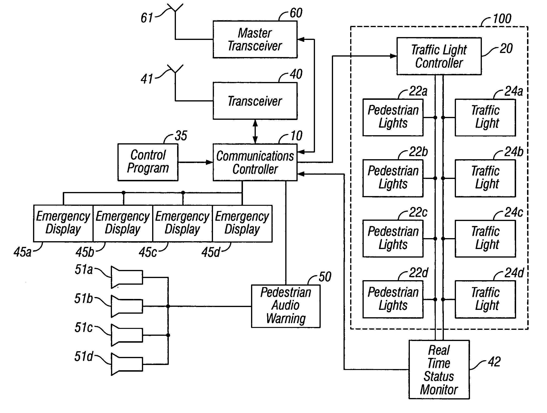
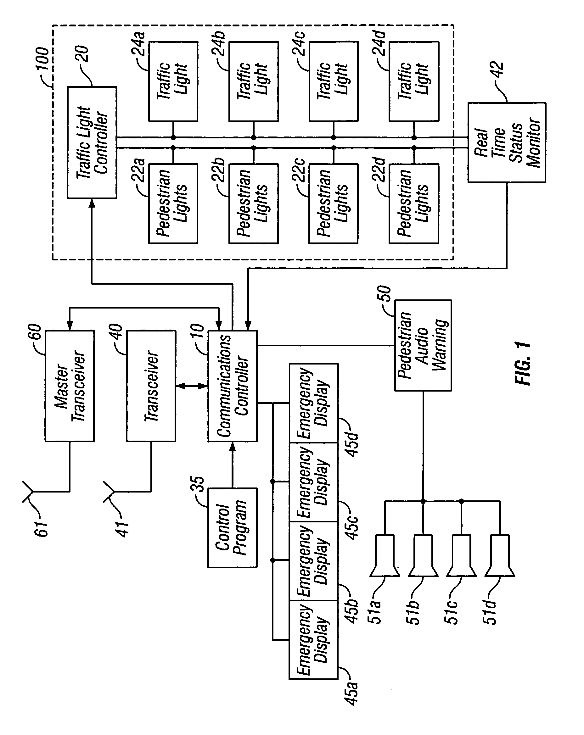
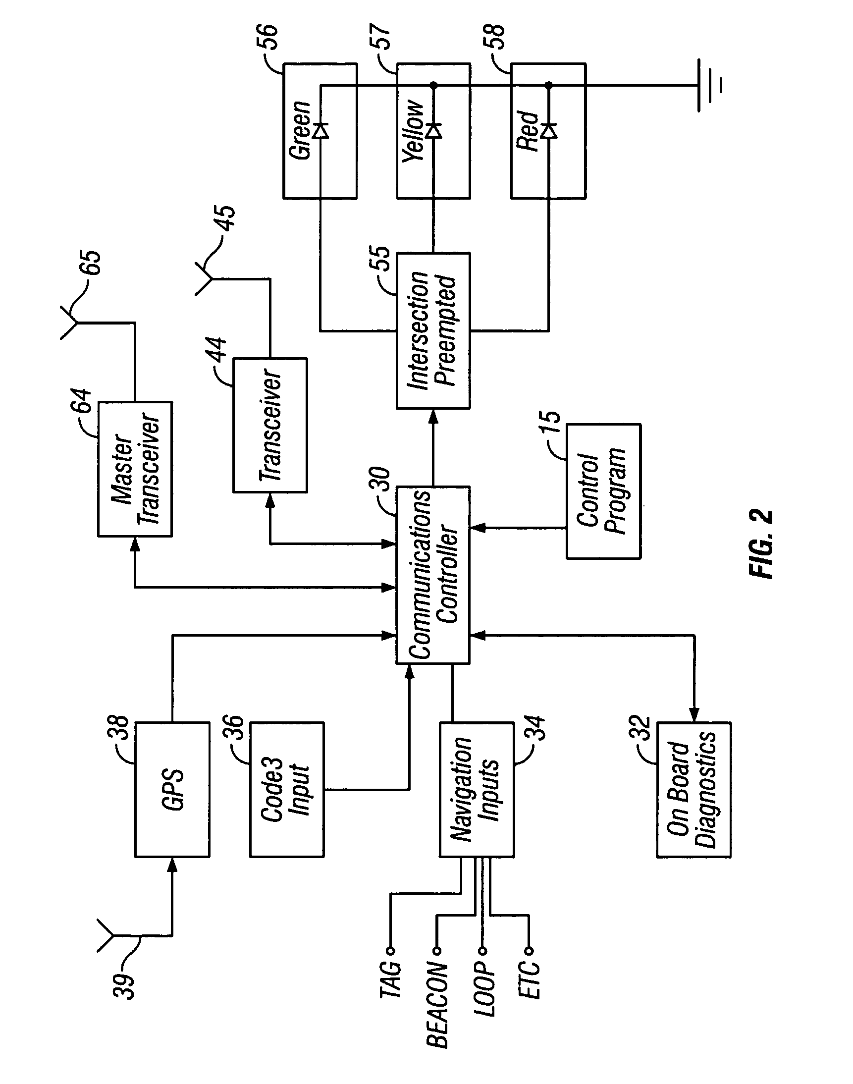
[0037]The details of the emergency vehicle traffic signal preemption system are illustrated in the block diagrams of FIGS. 1 and 2. FIG. 1 illustrates the functional details of the system at each intersection while FIG. 2 illustrates the functions of the system installed in an emergency vehicle.

[0038]Traffic light control system 100 at an intersection includes traffic light controller 20 that generates the appropriate sequence of on-time and off-time for the various traffic lights that controls vehicular and pedestrian traffic at an intersection. Traffic light controller 20 also has the capability to be forced by external signals into a mode that activates all “red” lights simultaneously to close the intersection allowing safe passage for emergency vehicles. Controller 20 is preferably a microprocessing circuit driving isolated lamp drivers but discrete designs are also feasible. Some intersections may be more complicated, controlling turn lanes with arrow lights, but the basic prin...


PUM


Abstract

An emergency vehicle traffic light preemption system for preemption of traffic lights at an intersection to allow safe passage of emergency vehicles. The system includes a real-time status monitor of an intersection which is relayed to a communications controller for transmission to emergency vehicles as well as to a central dispatch office. The system also provides for audio warnings at an intersection to protect pedestrians who may not be in a position to see visual warnings or for various reasons cannot hear the approach of emergency vehicles. A transponder mounted on an emergency vehicle provides autonomous control so the vehicle operator can attend to getting to an emergency and not be concerned with the operation of the system. Activation of a Code 3 situation provides communications with each intersection being approached by an emergency vehicle and indicates whether the intersection is preempted or if there is any conflict with other approaching emergency vehicles. On-board diagnostics handle various information including heading, speed, and acceleration sent to a communications controller which is transmitted to an intersection and which also simultaneously receives information regarding the status of an intersection.

Description

[0001]Priority of U.S. Provisional Application Ser. No. 60 / 403,916 filed Aug. 15, 2002 is hereby claimed.[0002]The invention described herein was made in the performance of work under a NASA contract and is subject to the provisions of Public Law 96-517 (35 U.S.C. 202) in which the Contractor has elected to retain title.BACKGROUND OF THE INVENTION[0003]1. Field of the Invention[0004]This invention relates to systems for controlling vehicle traffic signals to allow safe passage of emergency vehicles and more particularly relates to a system for autonomously preempting traffic signals at an intersection that includes a transponder, a real-time intersection monitor, and an audio alarm or warning system.[0005]2. Background Information[0006]Present systems used to preempt traffic signals and clear intersections for emergency vehicles responding to a life-saving event rely on: sound activation, optical activation, direct microwave activation, and a combination of all the above. All of the...

Claims


Application Information

Patent Timeline
IPC IPC(8): G08G1/07G08G1/095G08G1/087
CPCG08G1/087
Inventor BACHELDER, AARON D.FOSTER, CONRAD F.
Owner CALIFORNIA INST OF TECH
Learn More