

Gain control amplification circuit and terminal equipment having the same
- Summary
- Abstract
- Description
- Claims
- Application Information
AI Technical Summary
Benefits of technology
Problems solved by technology
Method used
Image

Examples
first embodiment
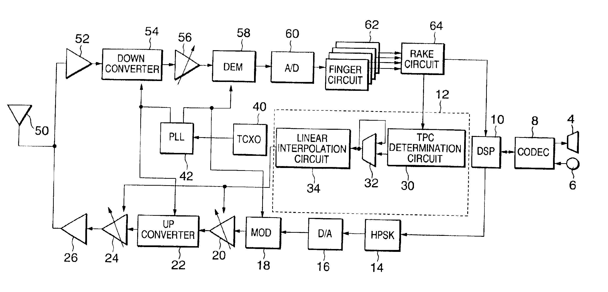
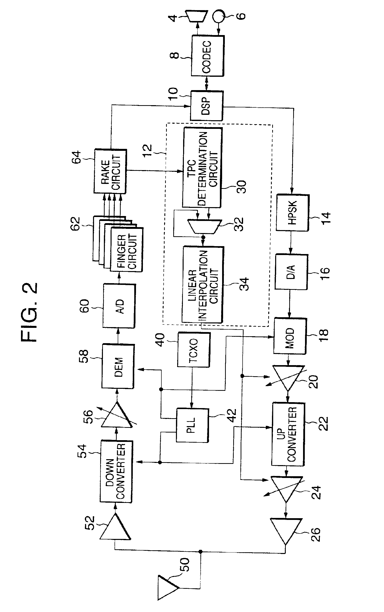
[0045]The schematic arrangement of a gain control amplification circuit according to the present invention will be described with reference to FIG. 2.
[0046]The circuit shown in FIG. 2 is the circuit of a CDMA radio device (terminal equipment) using a transmission / reception heterodyne scheme. The overall circuit arrangement of the terminal equipment will be described first.
[0047]An antenna 50 is connected to an LNA (Low Noise Amplifier) 52 to amplify an input reception signal. The output terminal of the LNA 52 is connected to a down converter 54 for converting the amplified reception signal into an intermediate frequency (to be referred to as an IF hereinafter).
[0048]The output terminal of the down converter 54 is connected to a reception section gain control amplifier (to be referred to as an RX-GCA hereinafter) 56 for amplifying the IF signal output from the down converter 54 to a predetermined level. The output terminal of the RX-GCA 56 is connected to a DEM (demodulator) 58 for d...
second embodiment
[0067]the present invention will be described next with reference to FIG. 3.
[0068]The same reference numerals as in the first embodiment described above with reference to FIG. 2 denote the same components in the second embodiment, and a detailed description thereof will be omitted.
[0069]The reception circuit system from an antenna 50 to a RAKE circuit 64 is almost the same as in the first embodiment, though a GCA control circuit 13 related to an IF-GCA 20 and RF-GCA 24 is different from that in the first embodiment.
[0070]The GCA control circuit 13 comprises a TCP determination circuit 30, adder 32, RF linear interpolation circuit 35, and IF linear interpolation circuit 37. TCP data is input to the TCP determination circuit 30. The output from the TCP determination circuit 30 is input to the adder 32 and added to the current transmission output value. The output value added by the adder 32 is input to the RF linear interpolation circuit 35 and IF linear interpolation circuit 37.
[0071...
third embodiment
[0085]FIG. 8 is a block diagram showing of a gain control amplification circuit according to the present invention.
[0086]In the third embodiment, when a wide transmission output control range is necessary, GCAs 20, 241, 242, . . . , 24n−1 of a plurality of stages, i.e., N stages (two or more stages) are provided, and N linear interpolation circuit 351, 352, . . . , 35n−1, and 38 are arranged in correspondence with the GCAs, respectively, thereby realizing the same effect as described above. In this case, GCAs 24 of a plurality of stages are preferably set on the output side of an up converter 22. However, the present invention is not limited to this.
[0087]In each of the above-described embodiments, the transmission circuit of a CDMA terminal equipment has been exemplified. However, the present invention is not limited to this example.
PUM
 Abstract
Description
Claims
Application Information