
Method for operating a casting-rolling plant

a technology of casting and rolling mill, which is applied in the direction of manufacturing tools, stock shearing machines,foundry moulding apparatus, etc., can solve the problems of gaps in production, rolling mill train rolling more quickly, and inability to fully exploit rolling mill train rolling capacity, etc., and achieve the effect of increasing throughpu

Inactive Publication Date: 2005-09-13
PRIMETALS TECH GERMANY
View PDF34 Cites 9 Cited by
  • Summary
  • Abstract
  • Description
  • Claims
  • Application Information

AI Technical Summary

Benefits of technology

[0008]Therefore, it is an object of the present invention to provide a method for operating a casting and rolling plant which allows a higher throughput to be achieved during the production of strip material.
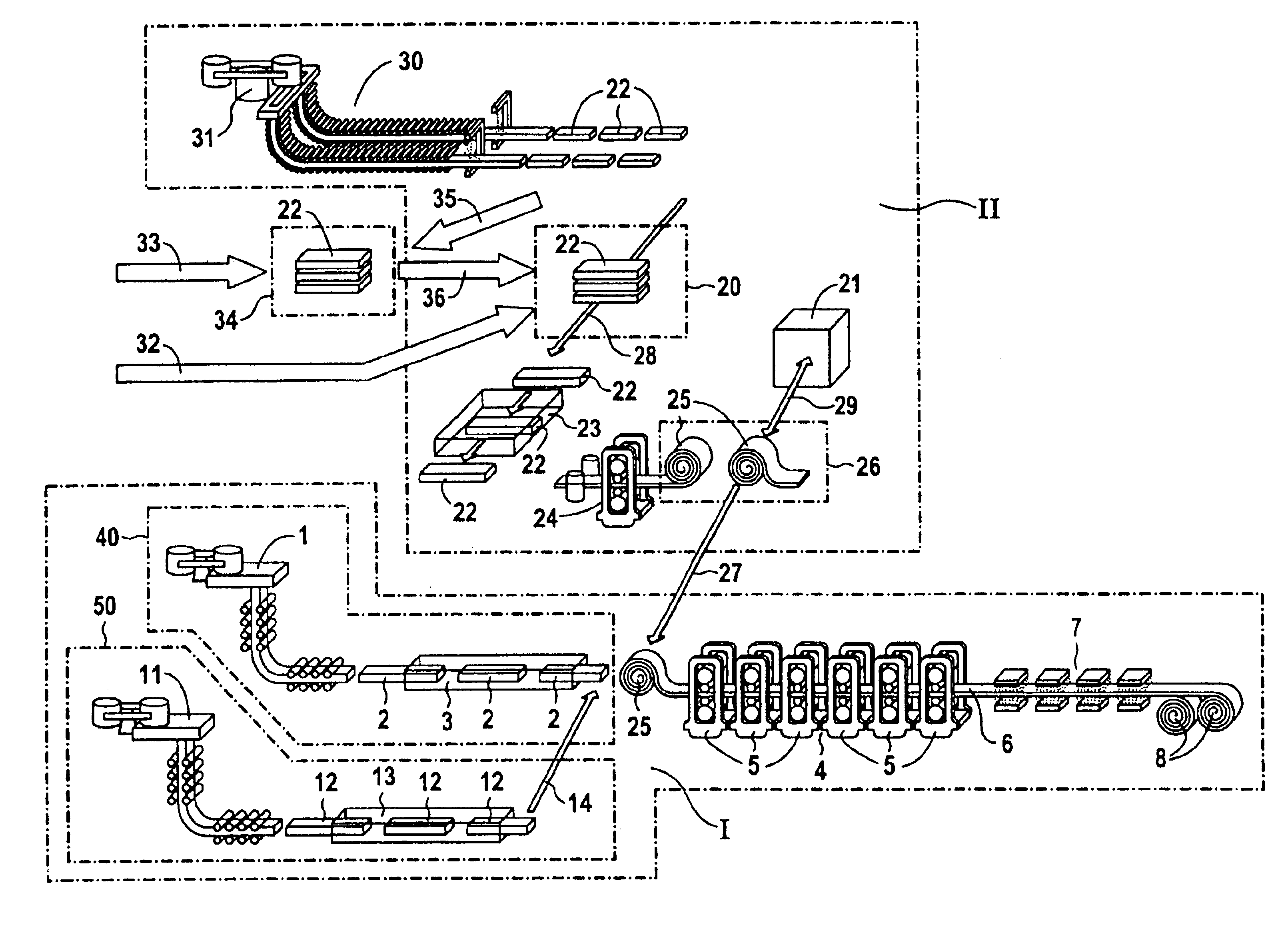
[0020]The invention provides a suitable production planning method which is matched to the nature of the widened configuration of the casting and rolling plant. The slabs supplied by the slab feed device are additionally rolled in the rolling mill train without the basic equipment of the specially configured casting and rolling plant having to be changed. This allows the quantitative throughput during the production of strip material to be significantly increased.
[0025]An additional conventional slab production line, which rolls thick slabs, by means of at least one heating furnace and by means of at least one (reversing) roughing stand, to form thin slabs and provides the latter to the rolling mill train via a holding furnace. This configuration will be selected if the additional slab production line is to produce steel grades which are not able to withstand high casting speeds, i.e. for example special steels. Therefore, a casting and rolling plant which is operated using the method according to the invention can supply standard steels and special steels with a high total annual production.

Problems solved by technology

In the known casting plants, the rolling capacity of the rolling mill train cannot be fully exploited over the course of time, since the casting capacity (casting speed and casting cross section) of the casting machine(s) cannot be increased beyond certain limits if technical and quality problems are to be avoided.
Despite full casting operation, this means that the rolling mill train rolls more quickly than the casting machine or machines are able to supply slabs.
A further reason for the limited production capacity of the known casting and rolling plants is that the two-strand casting installation or the two casting installations for technical reasons cannot produce at certain times, resulting in gaps in production.
The unused production gaps include, inter alia, the necessary idle times of the casting machines caused by the need to change the distributor, mold or segment, planned downtimes for maintenance work and unplanned downtimes caused by problems in casting operation.
This means that the rolling mill train then either cannot carry out any rolling at all or can only carry out rolling with increased pauses.
Therefore, the two slab production lines constitute a production bottleneck for the capacity of the rolling mill train, leading to a reduced annual production capacity of the casting and rolling plant.

Method used


Image

  • Method for operating a casting-rolling plant
  • Method for operating a casting-rolling plant

Examples


Embodiment Construction

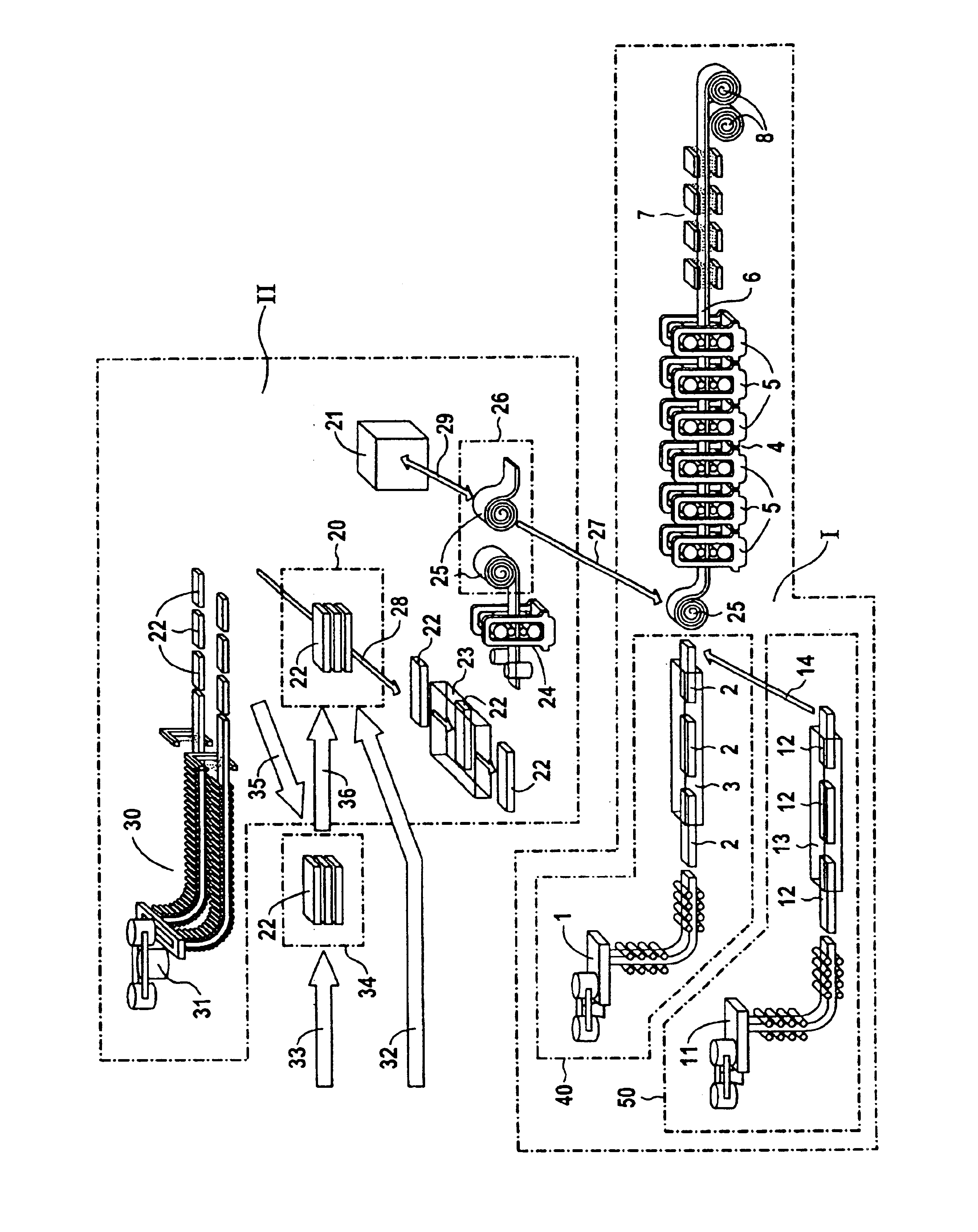
[0036]In the case of the casting and rolling installation illustrated in the drawing, the first production line I comprises a further casting machine 11. In manufacturing technology terms, the casting machine 11 is arranged parallel to the casting machine 1. The casting machine 11 likewise produces thin slabs 12. These thin slabs 12 are fed to a tunnel furnace 13 which is arranged within the first production line I, parallel with the tunnel furnace 3 in terms of manufacturing technology. The casting machine 11 and the tunnel furnace 13 together form a slab production line (casting installation), which is denoted by 50. The thin slabs 12 produced by the slab production line 50 are then likewise fed to the rolling mill train 4 (arrow 14).

[0037]The slab production lines 40 and 50 together form a two-strand casting installation.

[0038]A second production line II is arranged at least partially in parallel, in terms of manufacturing technology, with the first production line I. In the case...


PUM


Abstract

A casting-rolling plant and a method of operating a casting-rolling plant are disclosed. At least one slab production line (40, 50) and at least one mill train (4) as well as at least one slab feeding device (20) that is independent of the slab production line (40, 50) with respect to the production process are provided. In order to achieve a higher throughput in the production of strip material, the slab feeding device (20) takes over slab feed to the mill train (4) during a production break of the slab production line (40, 50) in accordance with logistic and / or manufacturing standards up to a maximum output possible.

Description

CROSS REFERENCE TO RELATED APPLICATION[0001]This application is a continuation of copending International Application No. PCT / DE02 / 00612 filed Feb. 20, 2002, which designates the United States, and claims priority to German application number 10109223.7 filed Feb. 26, 2001.TECHNICAL FIELD[0002]The invention relates to a method for operating a casting and rolling plant.BACKGROUND OF THE INVENTION[0003]In casting and rolling plants of this type, slabs are processed to form strip material. The known casting and rolling plants comprise at least one casting machine, the slabs of which are fed to at least one tunnel furnace without being temporarily stored. The tunnel furnace opens out into a rolling mill train (finishing train) with at least one rolling stand. In the rolling mill train, the slabs are rolled to form hot strips. On leaving the rolling mill train, the rolled hot strips are fed to at least one cooling section and are wound up onto at least one coiler.[0004]A casting and roll...

Claims


Application Information

Patent Timeline
IPC IPC(8): B21B1/46
CPCB21B1/466Y10T29/49988Y10T29/49991
Inventor DACHTLER, GERHARDPEUKER, THOMASSTURMER, UWE
Owner PRIMETALS TECH GERMANY
Learn More