Outflow-limiting device of fuel tank

Inactive Publication Date: 2005-09-13
TOYODA GOSEI CO LTD +1
View PDF11 Cites 32 Cited by
  • Summary
  • Abstract
  • Description
  • Claims
  • Application Information

AI Technical Summary

Benefits of technology

[0034]Preferably, the float valve has a double-seal structure in which an inner seal member is held in the float valve so as to move upward and downward as disclosed, for example, in JP-A-2-112658. In such a structure, there is eliminated a disadvantage that the float valve fails to move downward even when the liquid level descends after the float valve is brought into intimate contact with the communication opening portion leading to the canister. Therefore, the dynamic sealing ability is enhanced when the liquid surface of the fuel is vigorously disturbed to rise, and therefore the function of the cutoff valve is more effectively performed.
[0035]Preferably, an upwardly-open tubular portion is formed within the housing, and is disposed around the outer periphery of the float valve. By forming this tubular portion, the liquid fuel, passing through the through holes of a small diameter in the housing, impinge on the tubular portion, and the flow of the liquid fuel is regulated, so that the liquid fuel is prevented from intruding into the communication opening leading to the canister, and the inflow of the liquid fuel can be prevented more positively. Preferably, the level of this tubular portion is higher than the upper surface of the float valve located in its lower position in the normal condition.
[0036]Th

Problems solved by technology

However, there is a fear that the liquid fuel flows into the evaporation opening when the liquid level of the fuel moves up and down.
If the liquid fuel flowed as far as the canister, this liquid fuel would be adsorbed by the activated carbon, so that the adsorption of the vaporized fuel by the activated carbon would be adversely affected.
In the above device, there are provided the two float valves and the two communication passages, and therefore there is encountered a problem that it is difficult to design the device in such a manner that each of the two

Method used


Image

  • Outflow-limiting device of fuel tank
  • Outflow-limiting device of fuel tank
  • Outflow-limiting device of fuel tank

Examples


first embodiment

(First Embodiment)

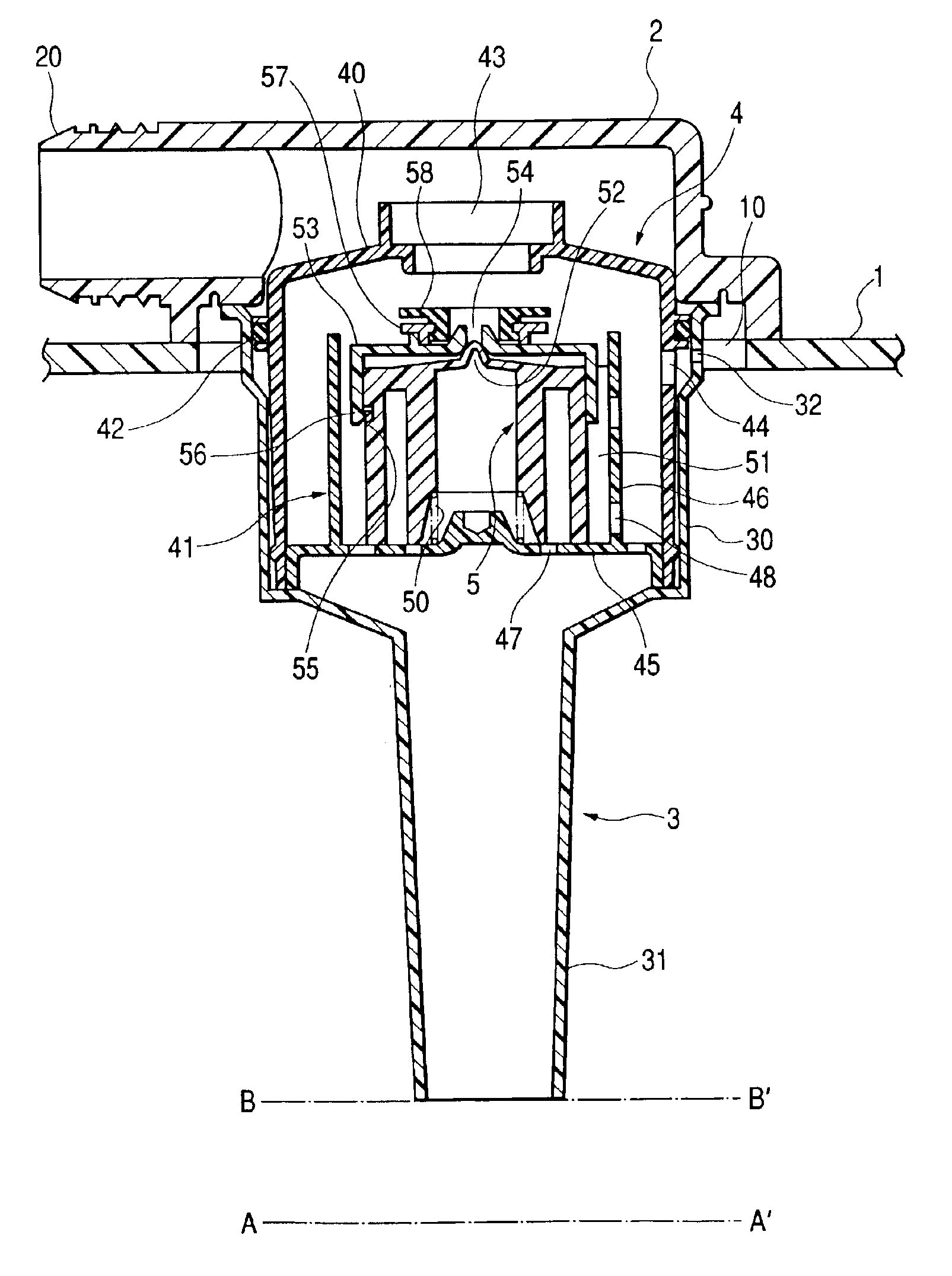
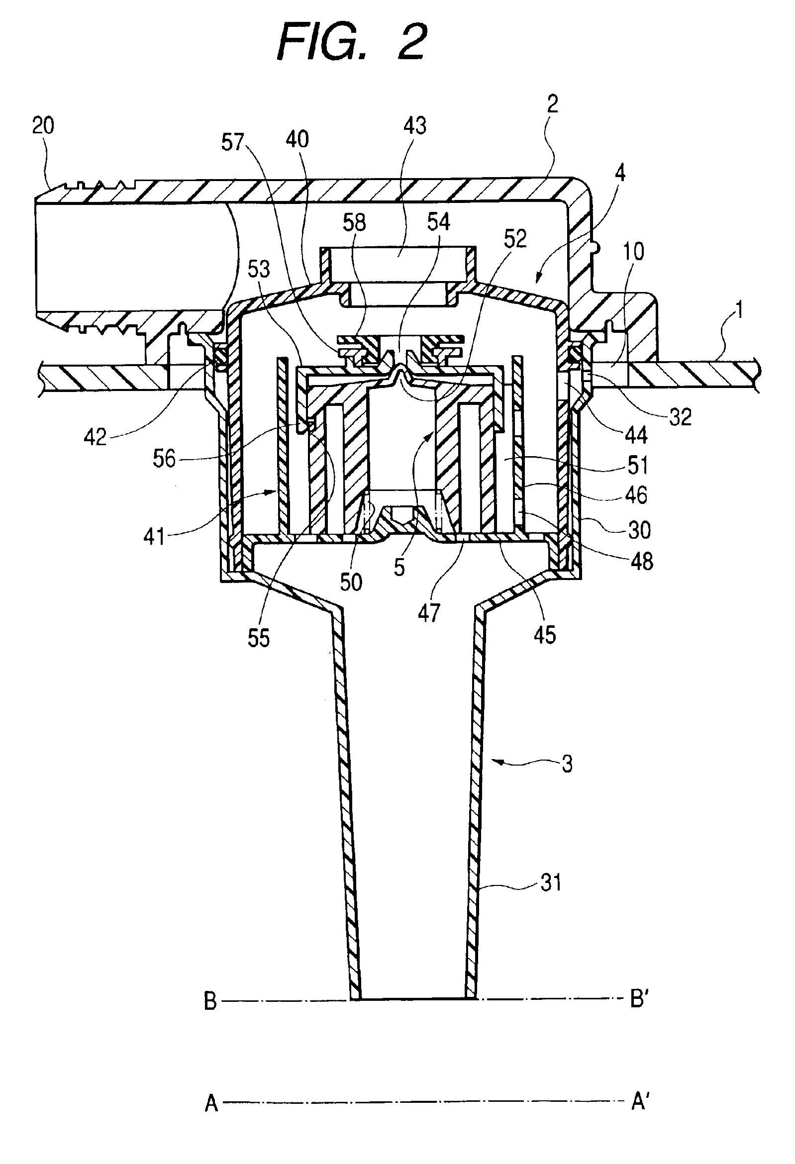
[0047]FIG. 1 is a front-elevational view of one preferred embodiment of a fuel outflow-limiting device of the present invention, FIG. 2 is a cross-sectional view thereof. This fuel outflow-limiting device mainly comprises a lid member 2, which is fixed by welding to an upper surface of an automotive gasoline tank 1 (made of a resin), and is disposed above an opening 10 formed in an upper wall of the gasoline tank 1, a tubular member 3 fixed by welding to a lower surface of the lid member 2, a housing 4 formed at an upper portion of the tubular member 3, and a float valve 5 mounted in the housing 4 so as to move upward and downward in a direction of the liquid level.

[0048]The lid member 2 is injection molded of a polyethylene resin and a polyamide resin, and includes a nipple 20 extending parallel to the upper surface of the gasoline tank 1, and a tube, communicating with a canister, is adapted to be fitted on this nipple 20.

[0049]The tubular member 3 is injection m...

second embodiment

(Second Embodiment)

[0062]FIG. 3 shows a second embodiment of a fuel outflow-limiting device of the invention. In this device, a housing 4 comprises an upper member 40 and a lower member 41. A tubular member 3 includes a tubular portion 33, and a flange portion 34 formed at one end of the tubular portion 33, and the flange portion 34 is welded to ends of the upper and lower members 40 and 41. Through holes 32 of a small diameter are formed through a peripheral wall of the upper member 40. The other construction is similar to that of the first embodiment.

[0063]In this device, also, similar operational effects as in the first embodiment can be achieved.

[0064]In the above embodiments, although the device is fixed to the gasoline tank 1 by welding the lid member 2 to the gasoline tank 1, a lid member 2 maybe fastened through a packing 21 to the gasoline tank 1 by bolts 6 or the like, as shown in FIG. 4. As shown in FIG. 5, the device can be fixedly mounted within the gasoline tank 1 in a...

third embodiment

(Third Embodiment)

[0065]FIG. 6 shows a third embodiment of a fuel outflow-limiting device of the invention. In this device, a relief mechanism 60 is provided on the outer side of the housing 4 within the cover member 2. The relief mechanism 60 is constituted by a bleeding passage 61 connecting the inside and the outside of the tank 1 and a ball valve 62 urged by a spring 63 and configured to open and close the bleeding passage 61 in accordance with the internal pressure of the tank 1. The ball valve 62 is usually urged in a direction toward the inside of the tank 1 so as to close the opening of the bleeding passage 61 on the side of the tank 1. However, as the internal pressure of the tank 1 is increased beyond a predetermined pressure, the ball valve 62 is pressurized and displaced against the urging of the spring 63 in a direction allowing the bleeding passage 61 to open. The relief mechanism 60 connects the inside and the outside of the gasoline tank 1. Thus the relief mechanism ...


PUM


Abstract

A device includes a housing fixed to an upper wall of a fuel tank, and having a communication opening in communication with a canister, a float valve received within the housing and floating on a fuel, and the float valve moving upward and downward so as to close and open the communication opening, and a tubular member communicating with the housing, and extending downwardly from the housing into the interior of the fuel tank. The device has through holes of a small diameter which are disposed near an upper wall of the fuel tank, and when the liquid level of the fuel in the fuel tank reaches the lower end opening of the tubular member, a pressure within the fuel tank increases, whereby the filling-up of the fuel tank is detected. When the liquid level of the fuel abnormally rises, the float valve closes the communication opening.

Description

[0001]The present application is based on Japanese Patent Application No. 2001-364172, which is incorporated herein by reference.BACKGROUND OF THE INVENTION[0002]This invention relates to improved structure of a cutoff valve and full-tank detection means provided in a tank, which is suitably adapted to fuel tank of an automobile.[0003]A vaporized-fuel circulation system, called an evaporation circuit, is provided in the vicinity of a fuel tank of an automobile. Vaporized fuel is fed from the fuel tank to an external canister by this evaporation circuit, and is adsorbed by activated carbon or the like to be temporarily stored therein, thereby preventing the increase of an internal pressure of the fuel tank due to the increase of the vapor pressure. The canister is connected to an engine, and the vaporized fuel is expelled from the activated carbon by a negative intake pressure of the engine, and is mixed with a fuel-air mixture, and the adsorbed vaporized fuel is thus again used as t...

Claims


Application Information

Patent Timeline
IPC IPC(8): B60K15/035B60K15/03F16K24/04F16K24/00B60K15/077F02M25/08F02M37/00
CPCB60K15/03519F16K24/044Y10T137/0874Y10T137/3099
Inventor MORI, EISHINAOKI, TOMOHIDEYOSHIDA, KEISUKEYAMADA, NORIHIROKIDO, KATSUYUKI
Owner TOYODA GOSEI CO LTD
Why Eureka
Try Eureka