Vibration-absorbing plate for golf club head

a golf club head and vibration-absorbing technology, which is applied in the field of vibration-absorbing plates for golf club heads, can solve the problems of a large increase in costs, and achieve the effect of improving gripping comfort and gaining the damping effect of golf club heads

Inactive Publication Date: 2005-09-13
FUSHENG PRECISION
View PDF11 Cites 48 Cited by
  • Summary
  • Abstract
  • Description
  • Claims
  • Application Information

AI Technical Summary

Benefits of technology

[0007]An object of the present invention is to provide a vibration-absorbing plate for a golf club head to gain damping effect of the golf club head and to improve gripping comfort.
[0008]Another object of the present invention is to provide a vibration-absorbing plate for a golf club head to improve strength of the golf club head.
[0010]Still another object of the present invention is to provide a vibration-absorbing plate for a golf club head to mitigate the need of strengthening the other portion of the golf club head.
[0011]Yet another object of the present invention is to provide a vibration-absorbing plate for a golf club head to mitigate the need of a weight member.
[0012]Still another object of the present invention is to provide a vibration-absorbing plate for a golf club head to cover unfinished area in a cavity in a rear side of the golf club head, thereby simplifying the processing procedure and cutting the processing cost.SUMMARY OF THE INVENTION

Problems solved by technology

Although the front member 20 and the rear member 21 can be tightly engaged together by explosive welding, the cost is largely increased.

Method used


Image

  • Vibration-absorbing plate for golf club head
  • Vibration-absorbing plate for golf club head
  • Vibration-absorbing plate for golf club head

Examples


first embodiment

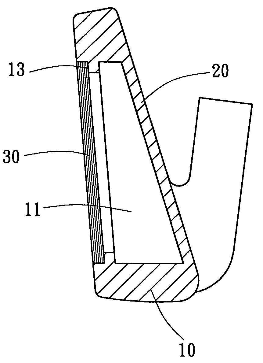
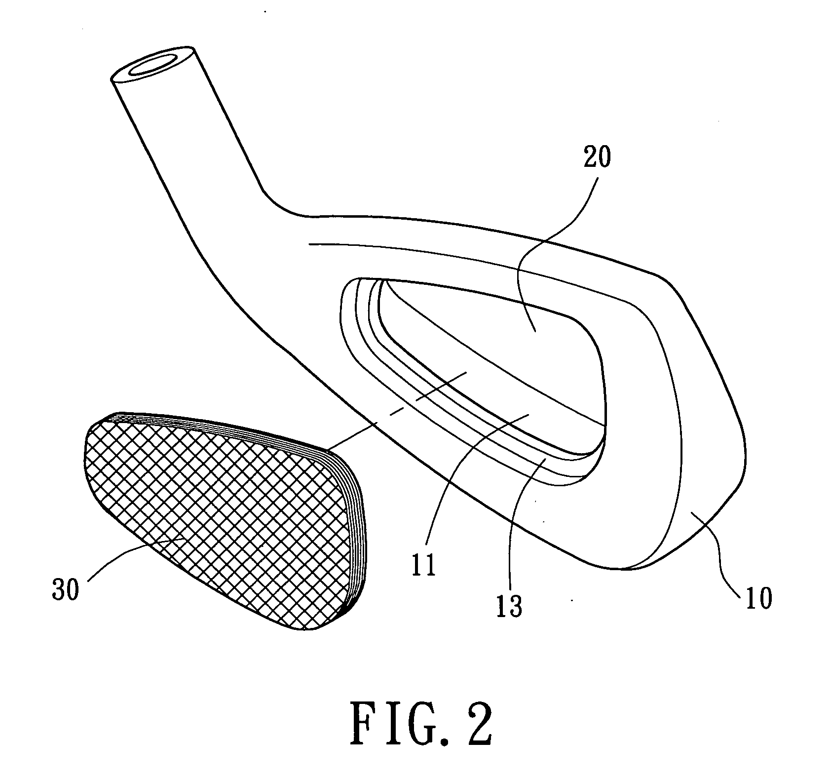
[0036]Referring to FIGS. 2 and 3, a golf club head in accordance with the present invention comprises a body 10, a striking plate 20, and a vibration-absorbing plate 30. The body 10 and the striking plate 20 are integrally formed from stainless steel, titanium alloy, carbon steel, special steel, etc. The striking plate 20 forms a front side of the body 10. A cavity 11 is defined in a rear side of the body 10 and has a stepped portion 13. The vibration-absorbing plate 30 is preferably a carbon fiber plate formed by means of pre-pressing a uni-direction cloth, plain-woven cloth, or twill cloth of graphite. The vibration-absorbing plate 30 is fixed on the stepped portion 13 by, e.g., bonding. The adhesive for bonding the vibration-absorbing plate 30 to the stepped portion 13 is preferably epoxy resin. Alternatively, the adhesive can be of one of solvent-release type, pressure-sensitive type, heat-sensitive type, and chemically-reactive type.

[0037]As illustrated in FIG. 3, the vibration...

second embodiment

[0039]FIGS. 4 and 5 illustrate the golf club head in accordance with the present invention. In this embodiment, the golf club head includes a body 10 and a striking plate 20 that are assembled together by an appropriate means and that are formed from different materials. The body 10 includes a recess 17 in a front side thereof, a cavity 11 in a rear side thereof, and an aperture 16 which connects the recess 17 to the cavity 11. The cavity 11 includes a stepped portion 13, and the recess 17 has a stepped portion 12.

[0040]The striking plate 20 is inserted into the recess 17 via the front side of the body 10 and supported by the stepped portion 12. The striking plate 20 can be fixed in the recess 17 of the body 10 by welding, bonding, insertion, or screwing. For example, the striking plate 20 and the body 10 can be engaged together by high-energy welding, such as laser welding, electric beam welding, plasma welding, or argon welding. The body 10 may further include an extension 14 exte...


PUM


Abstract

A golf club head includes a body having a cavity in a rear side thereof, a striking plate provided on a front side of the body, and a vibration-absorbing plate fixed in the cavity of the body and not in contact with the striking plate. The damping effect of the golf club head and gripping comfort are improved.

Description

BACKGROUND OF THE INVENTION[0001]1. Field of the Invention[0002]The present invention relates to a vibration-absorbing plate for a golf club head. In particular, the present invention relates to a vibration-absorbing plate for gaining damping effect of the body of the golf club head to thereby effectively absorb the vibrations generated as a result of striking a golf ball.[0003]2. Description of Related Art[0004]U.S. Pat. No. 5,967,903 discloses a golf club head with a sandwich structure and a method of making the same. As illustrated in FIG. 1 of the drawings which corresponds to FIG. 3 of U.S. Pat. No. 5,967,903, the golf club head includes a body 10, a striking assembly consisting of a front member 20 and a rear member 21. The body 10 is made of stainless steel or the like. Further, the body 10 includes a groove 17, a rear cavity 11, and an aperture 16 which connects the groove 17 to the rear cavity 11. The front member 20 and the rear member 21 are inserted via a front side of t...

Claims


Application Information

Patent Timeline
Patent Type & Authority Patents(United States)
IPC IPC(8): A63B53/04A63B53/06A63B59/00
CPCA63B53/047A63B53/0475A63B2209/02A63B2053/0416A63B2209/023A63B59/0092A63B53/0416A63B60/54
Inventor HOU, WEN-CHINGCHEN, CHAN-TUNGCHEN, YU-HONG
Owner FUSHENG PRECISION
Why Eureka
Try Eureka