Control system for the drive of a pto for an agricultural vehicle

a technology of control system and agricultural vehicle, which is applied in the direction of agricultural machines, thinning machines, transportation and packaging, etc., can solve the problems of limited service life of remaining drive elements and implements, no manual adjustment facility is envisaged, and no effect of high power uptak

Inactive Publication Date: 2005-09-13
BLUE LEAF I P INC +1
View PDF13 Cites 74 Cited by
  • Summary
  • Abstract
  • Description
  • Claims
  • Application Information

AI Technical Summary

Benefits of technology

[0018]Through the arrangement of a CVT transmission (continuously variable transmission) as a continuously variable gearbox in the drive train between the engine and the pto of an agricultural vehicle and its connection with control device with a processor, it has become possible to execute the acceleration and deceleration of the pto practically unrestricted as regards time. As a result, now smooth acceleration and deceleration even when operating implements with a very high power uptake is assured.
[0019]Driving of the CVT transmission by the control device dependent upon the most varied input signals after the acceleration of the pto brings about that this can be driven at preselectable continuously variable speeds via a potentiometer. This applies both to forwards and also reverse running of the pto. A functionally very important aspect of this is that the selected speed is attainable completely independently of the instantaneous speed of the engine of the agricultural vehicle. Thus the pto can be driven by the CVT transmission at maximum speed even from the idling speed of the engine. In addition, the CVT transmission is in a position to keep to the chosen speed of the pto very precisely, so that the driving of implements is assured without concessions, which for functional reasons requires exact drive speeds. On the other hand, however, with the CVT transmission it is also possible to run the pto as a ground speed pto, in which its speed is aligned directly proportional to the travelling speed of the agricultural vehicle. Finally, such a control system for the drive of a pto is employable also on agricultural vehicles with conventional and also CVT driving transmissions, since with it the special driving modes for the agricultural vehicle, which restrict the driving characteristics, have become superfluous.
[0020]According to features of the invention the same effect is to be achieved if the pto is driven by a continuously variably controllable hydraulic engine or electric motor. Naturally in that case the CVT transmission can be omitted.

Problems solved by technology

A further disadvantage in this control system is seen, in that no facility for a manually variable adjustment for the smoothness of engagement and disengagement is envisaged.
All the stated disadvantages are the reason that the hydraulically actuated clutch thus controlled, the remaining drive elements and the implement under these conditions exhibit only a limited service life, as acceleration proceeds too abruptly.
Furthermore, it is still to be criticised in this control mechanism, that in HTS or management operation respectively no influence was exerted on the engagement and disengagement of the hydraulically actuated clutch in relation to the desired lift height of the implement, which would however have been entirely desirable, given the variability of the implements that may be employed.
As a result on the one hand, damage to the drive shaft can occur, if this is not stopped in good time before a high angle of flexion is attained when the lift is raised, or if already in the presence of a high angle of flexion it is switched on again too soon.
On the other hand in the converse case, when lowering the lift the drive shaft is not switched on again in good time, lost time occurs, which diminishes the effective time of use of the tractor, and at the same time the risk exists that in that event the engine stalls, as the implement is already in contact with the ground before the pto turns.
However a further disadvantage arises in addition for this control mechanism, as in it no HTS or management operation is provided for.
In addition, both of the variant embodiments described in the foregoing have quite significant common disadvantages.
Thus acceleration and deceleration of the pto is mostly unsatisfactory, as the hydraulically actuated clutch permits only short wear times.
To improve this situation, therefore, very complicated and hence cost-intensive control systems are employed.
The necessity for the presence of a clutch, a gearbox with long gear levers and a brake leads necessarily to a large construction, which results in disadvantages in the design of the driver's cab.
In addition the clutch is an expendable part that wears out and incurs costs.
But also after acceleration of the pto, quite significant disadvantages arise for its drive through the lack of a control system in this area.
Thus through the direct driving connection between the engine of the tractor and the pto with interposition of the gearbox and the hydraulically actuated clutch a continuously variable selection of the pto speed independently of the engine speed is not possible.
This means that the engine must be driven constantly in a high-speed range, so that the fuel consumption of the engine is high and the driver is thereby subjected to unnecessary annoyance through noise.
In addition, it is still to be criticised that the PTO MODE to be found in some agricultural vehicles, by which is to be understood keeping the engine speed constant at all driving speeds, experiences limitations, as at a constant engine speed the driving transmission ratio can be altered only very slowly and hence the vehicle becomes sluggish.
In the case, which occurs not seldom in practice, that the speed of the engine drops also the maximum speed of the pto is limited.
Finally, with such a drive the mode of working of the pto as an accurate ground speed pto cannot be realised.
A very important disadvantage of this drive is also that reversal of the direction of rotation of the pto is not possible.

Method used


Image

  • Control system for the drive of a pto for an agricultural vehicle
  • Control system for the drive of a pto for an agricultural vehicle
  • Control system for the drive of a pto for an agricultural vehicle

Examples


Embodiment Construction

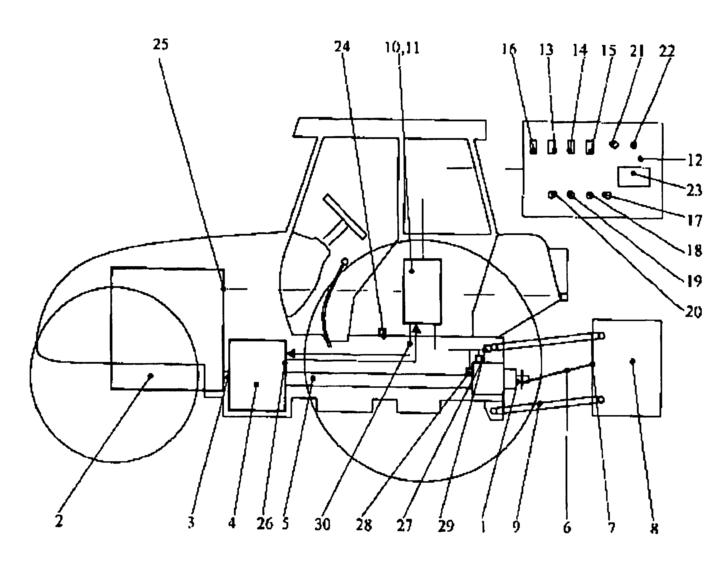
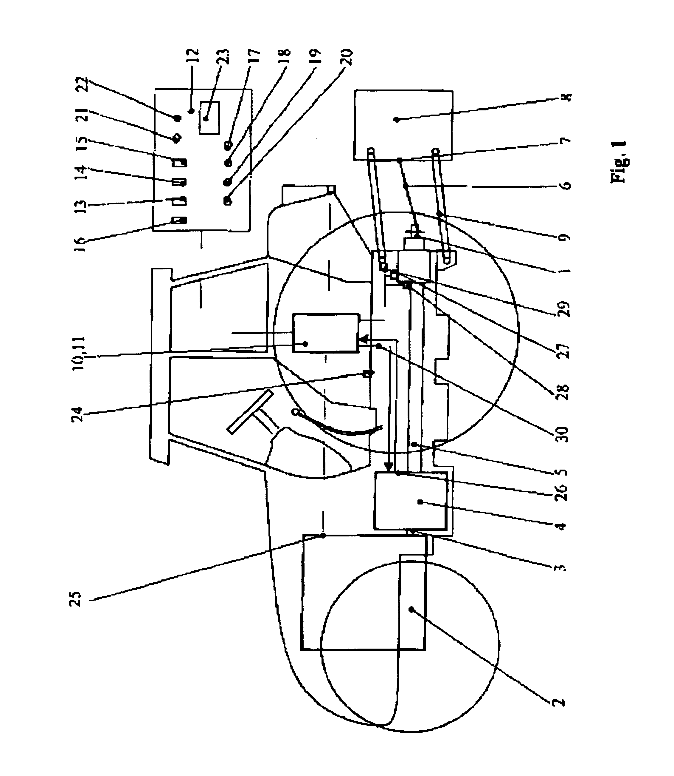
[0041]In FIG. 1 are to be seen in the side view of the left side of the tractor, viewed in the direction of travel, the drive train for driving the pto (1), which starts out from the engine (2) and is connected to the CVT transmission (4) via a shaft (3). With this CVT transmission (4) it concerns a continuously variably operating transmission. The drive train continues through an intermediate shaft (5) up to pto of the tractor. On the pto at one end a drive shaft (6) is attached, which is connected at its other end to drive the pto stub (7) of an implement (8) built onto the tractor, which in this example is suspended on the lift (9) at the rear of the tractor.

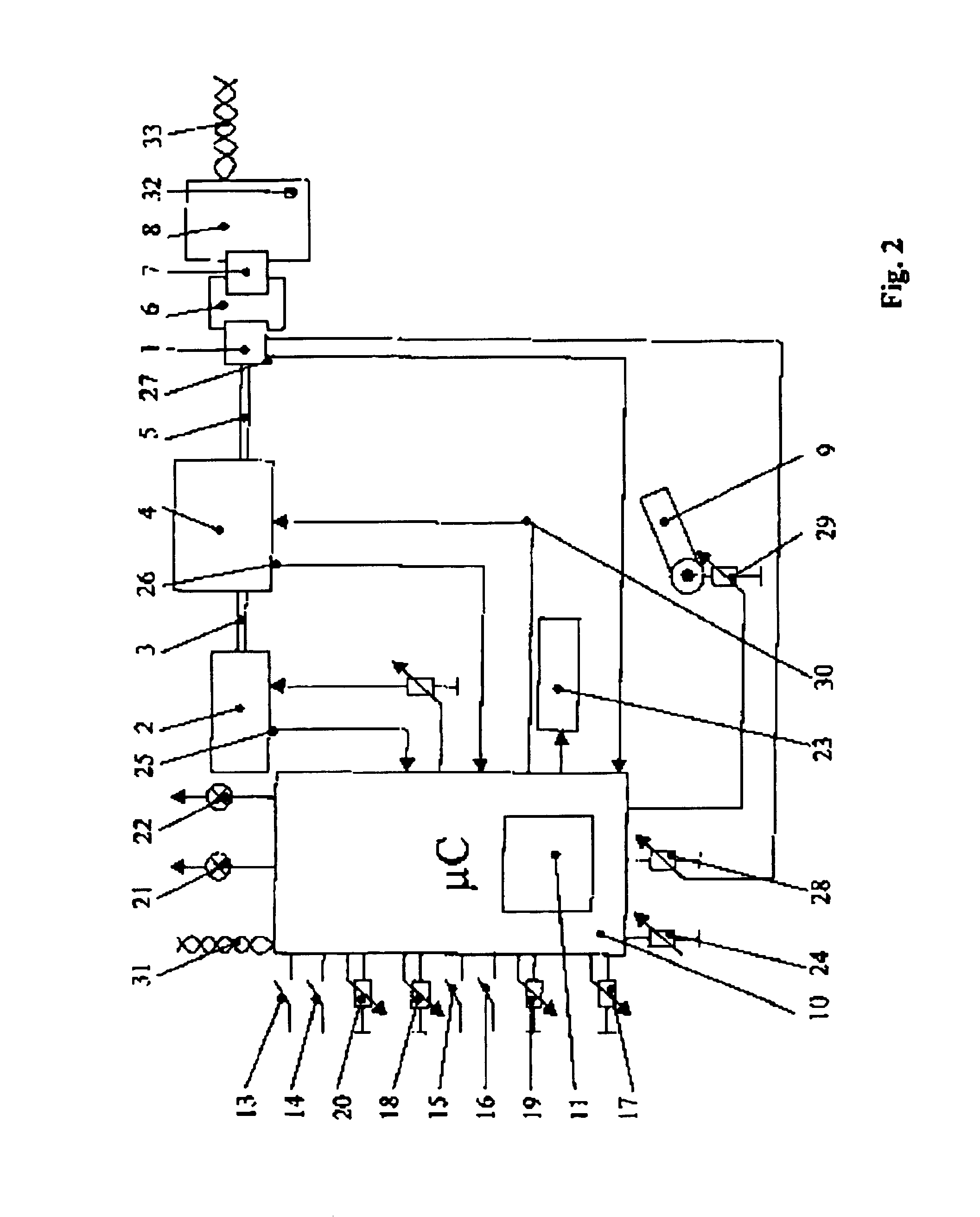
[0042]An important component for the control system for the drive of the pto (1) is a control device (10), in which a processor (11) is installed for processing a multitude of input signals and for passing on output signals to the CVT transmission (4). A part of the input signals comes from the control and display unit (12) w...


PUM


Abstract

A control system for the drive of a power take-off mechanism on an agricultural tractor that records machine-specific values of the implement attached to the tractor. The drive train between the tractor engine and the power take-off includes a CVT transmission. The control device is connected with a processor via a signal lead for receiving its output signals. The control device is connected for the formation of output signals via input leads with switches, controls, sensors, and actuators for the tractor to read the machine specific parameters of the attached implement.

Description

BACKGROUND OF THE INVENTION[0001]The present invention relates to a control system for the drive of a power take-off mechanism on an agricultural vehicle, and, particularly, a tractor having a CVT transmission and a control for reading machine specific values of an implement attached to the tractor.[0002]The drive of a pto on a tractor, which in principle coincides with such drives on all the other agricultural vehicles, is at present constructed in such a way that a gear box is connected to its engine for producing the speeds of 540, 750, 1000 or 1400 rpm which are usual in practice. Its drive shaft is connected to the input shaft by means of a hydraulically actuated clutch, to which pressure is admitted from the hydraulic circuit of the tractor via a solenoid valve, This drive train continues through the output shaft of the hydraulically actuated clutch, on which a brake of any desired type is arranged, up to the pto of the tractor.[0003]At one end of the pto a drive shaft is atta...

Claims


Application Information

Patent Timeline
Patent Type & Authority Patents(United States)
IPC IPC(8): A01B61/00A01B61/02B60K25/00
CPCA01B61/025B60K25/00B60W30/1888Y10T477/619Y10S180/90Y10T477/653
Inventor HRAZDERA, OLIVER
Owner BLUE LEAF I P INC
Why Eureka
Try Eureka