Excitation circuit and control method for flux switching motor

a technology of flux switching motor and excitation circuit, which is applied in the direction of motor/generator/converter stopper, electronic commutator control, dynamo-electric converter control, etc., can solve the problems of wasting power, snubbing circuit, and dissipating a fair amount of power, so as to improve the torque/speed performance of the motor

Inactive Publication Date: 2005-09-13
BLACK & DECKER INC
View PDF29 Cites 66 Cited by
  • Summary
  • Abstract
  • Description
  • Claims
  • Application Information

AI Technical Summary

Benefits of technology

[0013]The above and other objects are provided by an excitation circuit for a flux switching motor in accordance with a preferred embodiment of the present invention. The excitation circuit includes a switching circuit comprising a plurality of electronic switching devices configured in an H-bridge arrangement with an ar...

Problems solved by technology

Such a snubber circuit, however, has to dissipate a fair amount of power, which represents wasted power, each time current is switched through one of the armature windings or through portions of a single bifilar winding.
The copper utilization of such a scheme is also very low.
However, without the aluminum electrolytic capacitor, typically referred to as a “bulk” capacitor, starting of a flux switching motor from rest may be very slow and non-uniform.
Additionally, without such a bulk capacitor, it can take an unacceptably long time for the motor to reach its operating speed.
In many applications, such as with power tools such as table saws or mitre saws, it would be undesirable for the user to have to wait several seconds or more before the motor reached its operating speed before the ...

Method used


Image

  • Excitation circuit and control method for flux switching motor
  • Excitation circuit and control method for flux switching motor
  • Excitation circuit and control method for flux switching motor

Examples


Embodiment Construction

[0029]The following description of the preferred embodiment(s) is merely exemplary in nature and is in no way intended to limit the invention, its application, or uses.

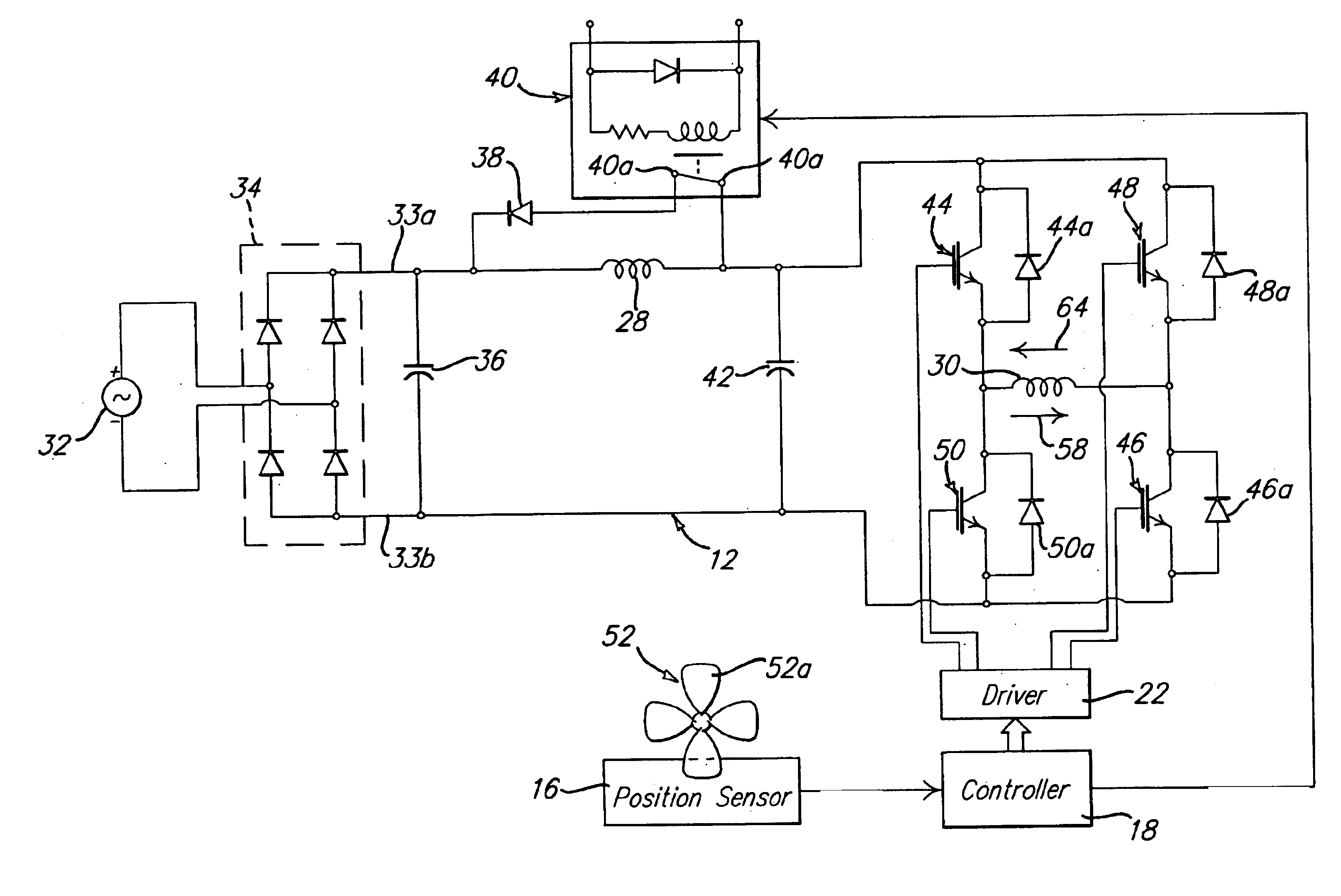
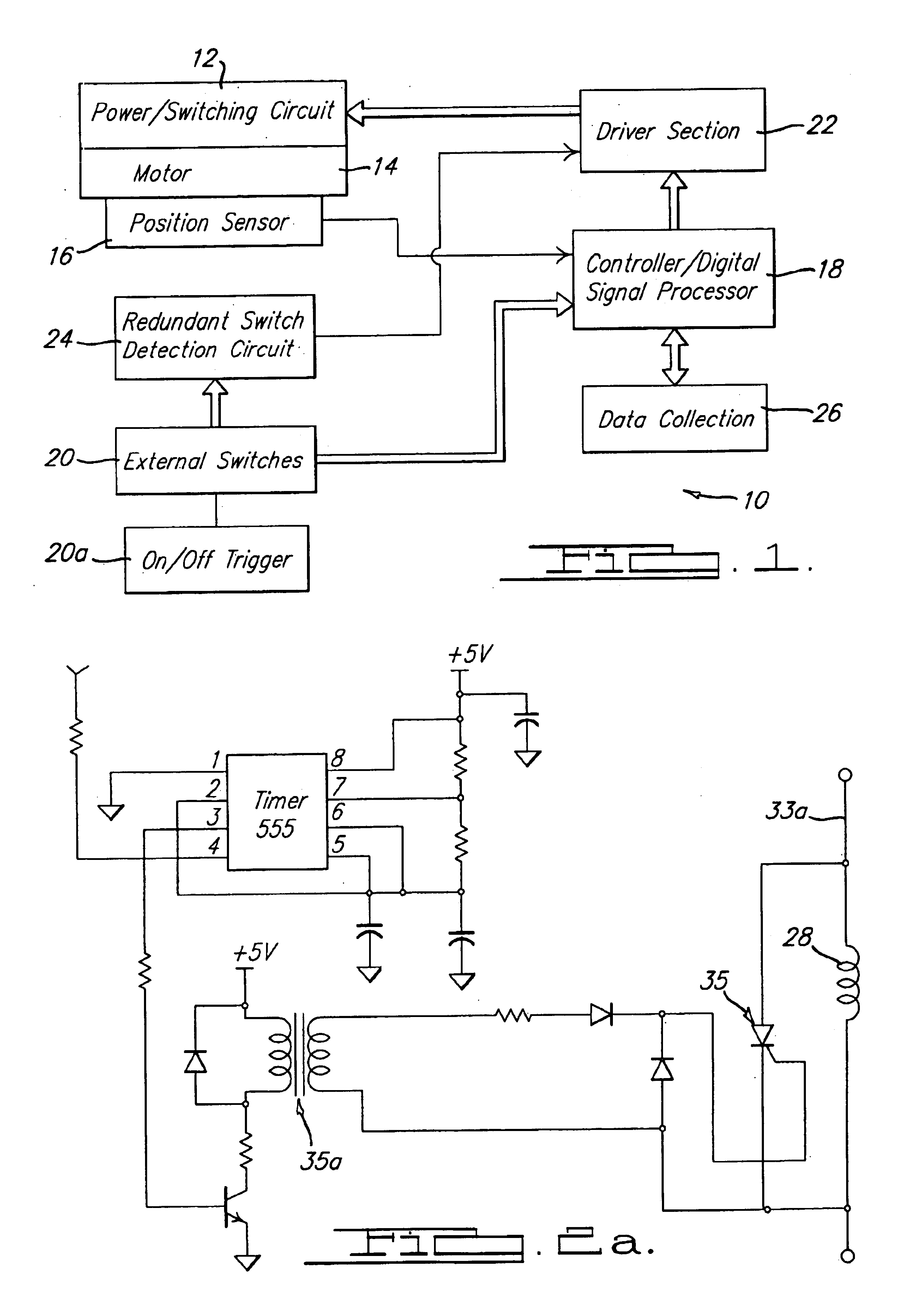
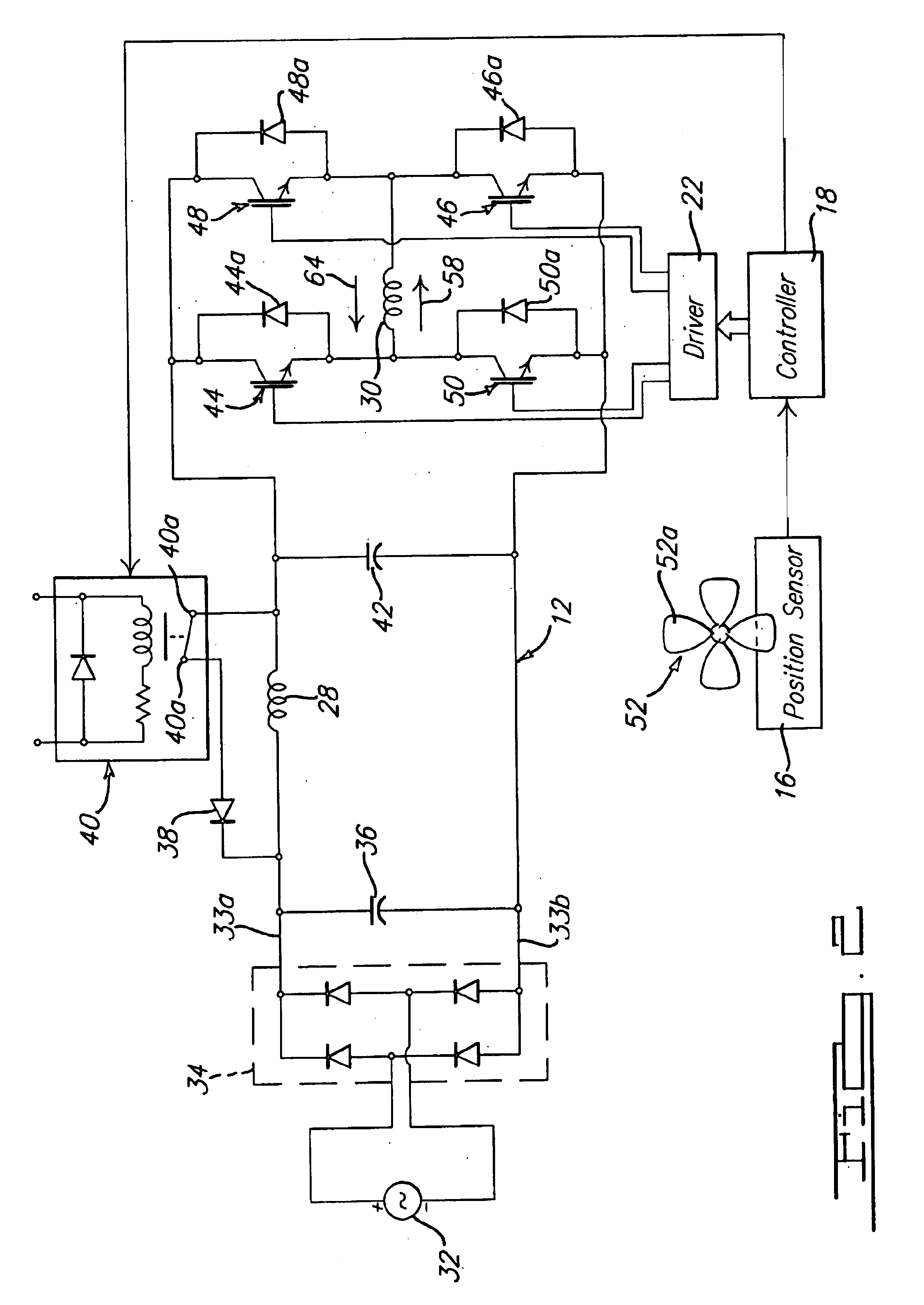
[0030]Referring to FIG. 1, there is shown an excitation system 10 in accordance with a preferred embodiment of the present invention. The system 10 generally comprises a power switching circuit 12 in communication with a flux switching motor 14. The motor 14 comprises a conventional flux switching motor having a stator with a plurality of poles, and in one preferred form a plurality of four poles, a fully-pitched field winding and a fully pitched armature winding. The number of turns of the field and armature windings may vary but in one preferred form the motor 14 comprises a field winding having 40 turns per coil and an armature winding having 20 turns per coil. In one preferred form, the stator has a pair of consequent poles as a result of arranging the armature winding in two parallel portions.

[0031]The motor 14 a...


PUM


Abstract

An excitation circuit for a flux switching motor. The circuit includes a low-value film capacitor across the DC side of a bridge rectifier. A plurality of electronic switches are arranged in an H-bridge configuration for switching current flow through an armature winding of the motor in accordance with a PWM control scheme and single-pulse control scheme controlled by a microcontroller. A start-up diode is placed across the field winding of the motor and is electronically switched out of the circuit after a startup phase of the motor has completed. The circuit implements armature energy recirculation through the field winding during startup to promote more uniform and quicker startup of the motor. The use of a film capacitor improves the power factor of the circuit, helps to eliminate the introduction of harmonics into the AC voltage source, and helps in mitigating EMI. Reverse commutation is used to bring the motor to a quick stop when it is powered off.

Description

CROSS REFERENCE TO RELATED APPLICATION[0001]This application is a continuation-in-part application of U.S. Ser. No. 10 / 213,777, filed Aug. 6, 2002 now abandoned, presently pending, which claims priority from U.S. provisional application Ser. No. 60 / 310,382, filed Aug. 6, 2001, the entire contents of which are hereby incorporated by reference into this application.FIELD OF THE INVENTION[0002]The present invention relates to excitation circuits for electric motors, and more particularly to an excitation circuit and a control method for a flux switching motor to control the startup and operation of the motor.BACKGROUND OF THE INVENTION[0003]Flux switching motors are characterized by an unwound, salient pole rotor and two sets of fully pitched windings on the stator. One of these sets of windings, the field, carries substantially unidirectional current. The other set, the armature, is excited by bidirectional current, the polarity of which is determined by the rotor position.[0004]Flux ...

Claims


Application Information

Patent Timeline
IPC IPC(8): H02P6/08H02P6/00H02P6/20H02KH02P1/00H02P6/14H02P25/08
CPCH02P6/085H02P6/142H02P6/20H02P25/082H02P25/0925H02P6/15
Inventor GORTI, BHANU
Owner BLACK & DECKER INC
Why Eureka
Try Eureka