Phase interpolator to interpolate between a plurality of clock phases

a phase interpolator and clock phase technology, applied in pulse generators, pulse manipulation, pulse techniques, etc., can solve problems such as prone to frequency distortion, analog loop filter consumes a substantial amount of on-die area, and classic dll based tracking architectures also present problems

Inactive Publication Date: 2005-09-13
INTEL CORP
View PDF3 Cites 63 Cited by
  • Summary
  • Abstract
  • Description
  • Claims
  • Application Information

AI Technical Summary

Problems solved by technology

This can be characterized as the problem, in digital communications, of transferring digital signals between multiple clock timing domains.
Hence it is prone to frequency distortions introduced through very low levels of noise on the control lines.
The analog loop filter consumes a substantial amount of on-die area.
Classic DLL based tracking architectures also present problems.
These also are prone to frequency distortion introduced t

Method used


Image

  • Phase interpolator to interpolate between a plurality of clock phases
  • Phase interpolator to interpolate between a plurality of clock phases
  • Phase interpolator to interpolate between a plurality of clock phases

Examples


Embodiment Construction

[0012]Embodiments of methods and systems for clock recovery are described. In the following description, for purposes of explanation, numerous specific details are set forth to provide a thorough understanding of the present invention. It will be appreciated, however, by one skilled in the art, that the present invention may be practiced without these specific details. In other instances, structures and devices are shown in block diagram form. Furthermore, one skilled in the art can readily appreciate that the specific sequence in which methods are presented and performed are illustrative and it is contemplated that the sequences can be varied and still remain within the spirit and scope of the present invention.

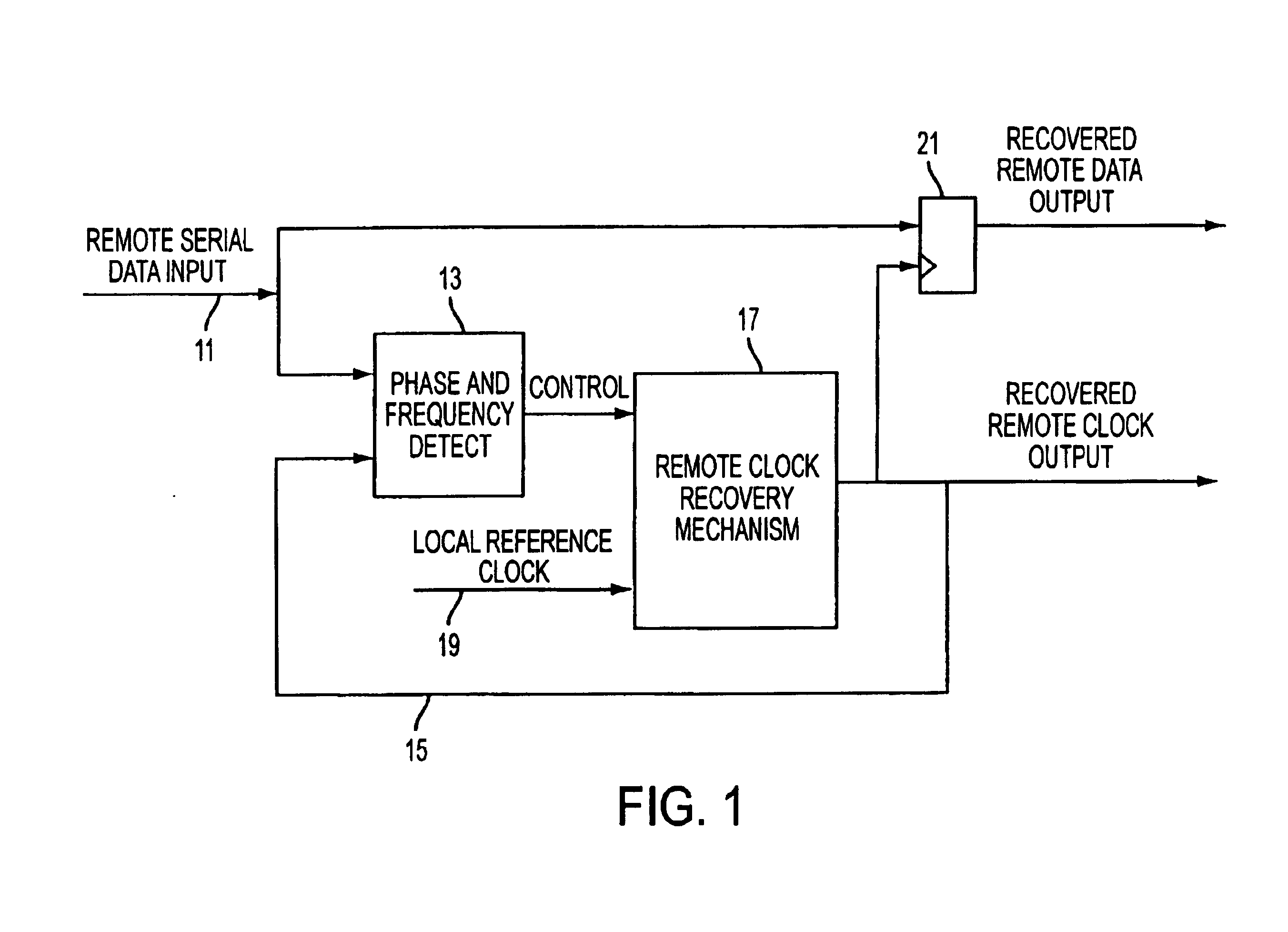
[0013]FIG. 1 is a block diagram of a typical tracking receiver in which embodiments of the phase interpolator of the present invention may be used. Remote serial data on line 11 is input to a phase and frequency detect circuit 13, which has as a second input the recovered re...


PUM


Abstract

A phase interpolator interpolates between a plurality of clock phases using a plurality of switching legs coupled to a common output. Each switching leg includes a pair of differential switching transistors each having a gate and two additional terminals, one of which is coupled to said common output. The gates are coupled to respective ones of the plurality of clock phases and their complements. Tails couple the other terminals of said switching transistors to ground. Each tail made up of a plurality of transistors. A load coupling the common output to a voltage.

Description

FIELD OF THE INVENTION[0001]Embodiments of the present invention relate to phase interpolators in general and more particularly to such an interpolator useful in recovering a clock from serial data in a tracking receiver.BACKGROUND OF THE INVENTION[0002]In many data communication arrangements, no separate clock signals are transmitted. This requires recovering the clock at the receiving end in order to then recover the data. This can be characterized as the problem, in digital communications, of transferring digital signals between multiple clock timing domains. Multiple clock timing domains include the clock timing domain of a transmitting device as well as the clock timing domain of a receiving device. It is not unusual to transmit digital signals between clock timing domains having nearly the same underlying frequency clock, but different or varying phases with respect to each other.[0003]In the prior art, clock recovery circuits provide clock recovery from serial data streams in...

Claims


Application Information

Patent Timeline
IPC IPC(8): H03L7/08H03L7/081H03K5/13H03K5/00
CPCH03L7/0814H03K5/13H03K2005/00286
Inventor DUNNING, DAVIED S.ABHAYAGUNAWARDHANA, CHAMATHDROTTAR, KENJENSEN, RICHARD S.GLENN, ROBERT
Owner INTEL CORP
Why Eureka
Try Eureka