
Apparatus for clock data recovery

a clock signal and data recovery technology, applied in the field of clock data recovery, can solve the problems of device failure, loop divergence, and ineffective approach for correcting frequency offsets in clock signals, and achieve the effects of improving reliability, stability and effectiveness of existing transceivers and networks, and reducing the amount of additional circuitry

Inactive Publication Date: 2007-11-13
MARVELL ASIA PTE LTD
View PDF11 Cites 45 Cited by
  • Summary
  • Abstract
  • Description
  • Claims
  • Application Information

AI Technical Summary

Benefits of technology

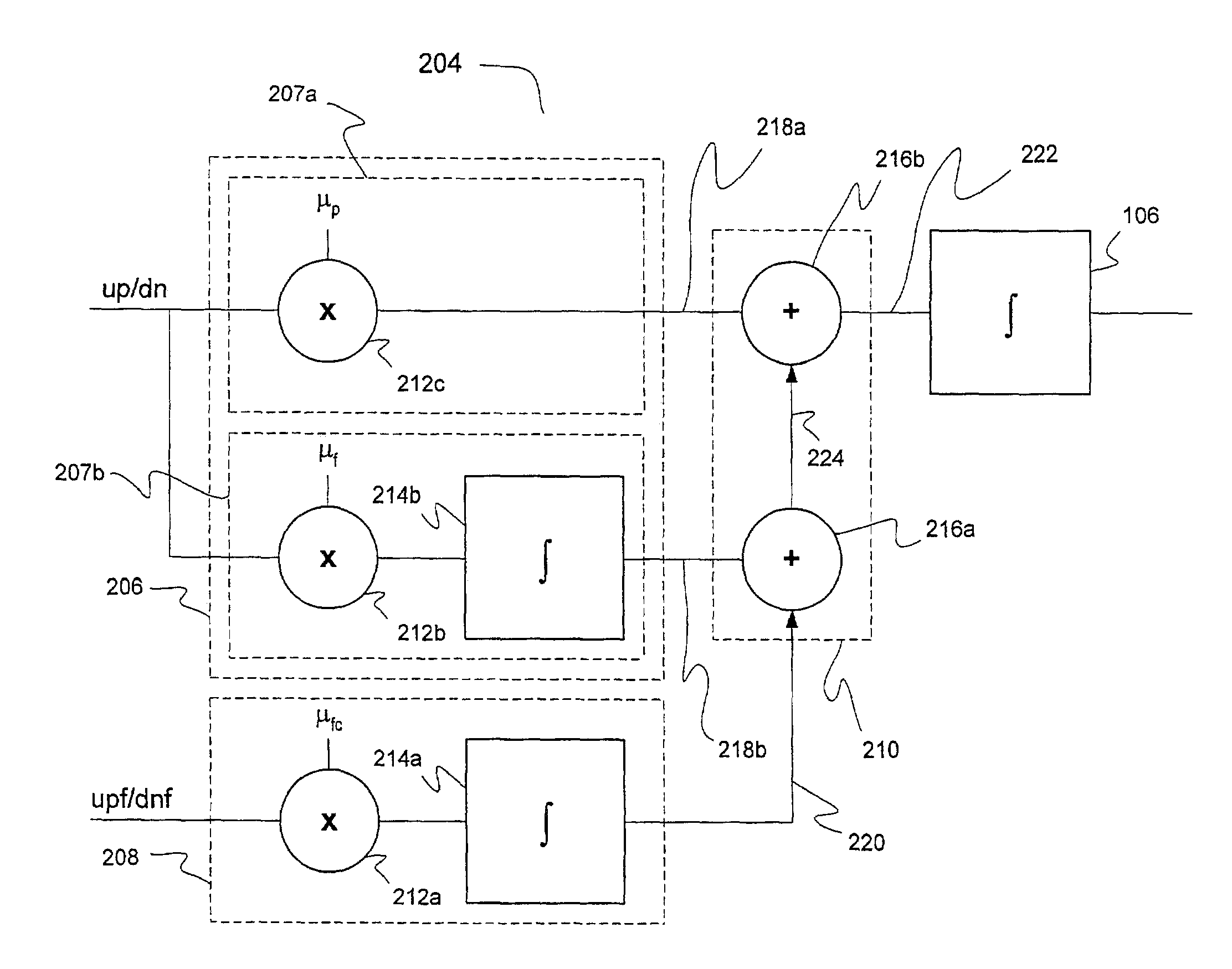
[0015]The present invention advantageously provides significantly greater coverage against one or more frequency-related failure modes associated with clock data recovery circuitry, particularly the nonconvergence / clock runaway problem described above. The present invention may also be used to improve existing designs and logic, with minimal or no changes. Thus, the present invention advantageously enables one to improve the reliability, stability and effectiveness of existing transceivers and networks, with a minimal amount of additional circuitry.

Problems solved by technology

Furthermore, the logic that generates phase adjustment control signal up / dn can only determine whether a phase transition has occurred.
However, this approach is not 100% effective for correcting frequency offsets in a clock signal recovered from a data stream.
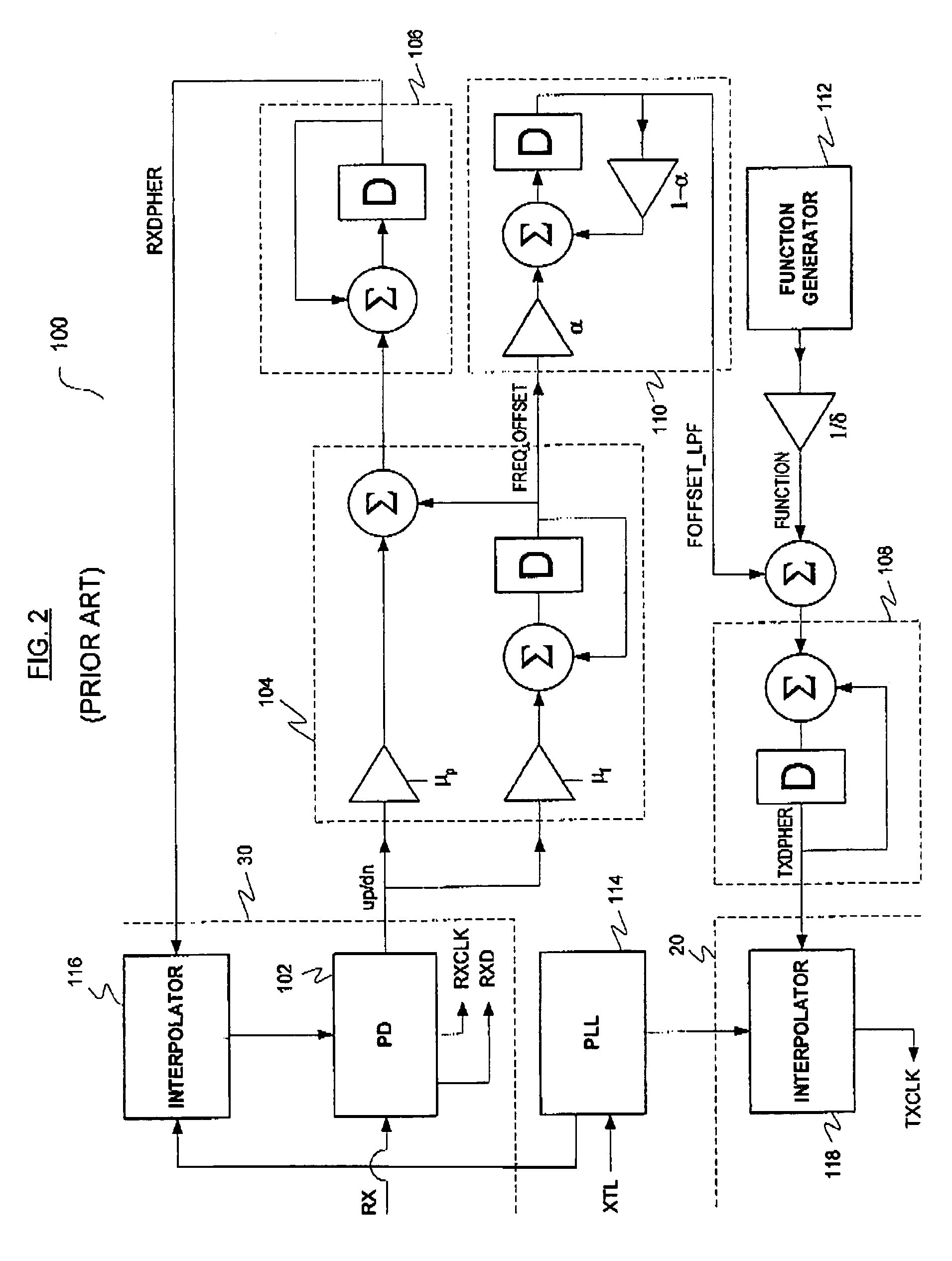
There is a potential error condition in the clock data recovery loop of FIG. 2 where the frequency offset between the reference clock and the incoming data stream is sufficiently large to cause the loop to diverge.
In such a case, a runaway condition may result, leading to device failure and a need to reset the device.
As network speeds increase, the potential failure modes associated with clock data recovery make designing stable, flexible, adaptable and effective clock data recovery circuitry challenging.

Method used


Image

  • Apparatus for clock data recovery
  • Apparatus for clock data recovery
  • Apparatus for clock data recovery

Examples


Embodiment Construction

[0025]Reference will now be made in detail to the preferred embodiments of the invention, examples of which are illustrated in the accompanying drawings. While the invention will be described in conjunction with the preferred embodiments, it will be understood that they are not intended to limit the invention to these embodiments. On the contrary, the invention is intended to cover alternatives, modifications and equivalents, which may be included within the spirit and scope of the invention as defined by the appended claims. Furthermore, in the following detailed description of the present invention, numerous specific details are set forth in order to provide a thorough understanding of the present invention. However, it will be readily apparent to one skilled in the art that the present invention may be practiced without these specific details. In other instances, well-known methods, procedures, components, and circuits have not been described in detail so as not to unnecessarily ...


PUM


Abstract

Circuits, architectures, a system and methods for clock data recovery. The circuit generally includes (a) a clock phase adjustment circuit, receiving clock phase information and providing a clock phase adjustment signal, (b) a clock frequency adjustment circuit, receiving clock frequency information and providing a clock frequency adjustment signal, and (c) an adder circuit, receiving the clock phase adjustment signal and the clock frequency adjustment signal, and providing a clock recovery adjustment signal. The architectures and / or systems generally comprise those that include a clock data recovery circuit embodying one or more of the inventive concepts disclosed herein. The method generally comprises the steps of (1) sampling the data stream at predetermined times, (2) generating clock frequency information and clock phase information from sampled data, and (3) altering a frequency and / or a phase of the clock signal in response to the clock frequency information and the clock phase information. The present invention prevents or reduces the likelihood of the potential nonconvergence / clock runaway problem, advantageously with minimal or no changes to existing designs and logic. The present invention further advantageously improves system stability, reliability and performance with a minimum of additional circuitry.

Description

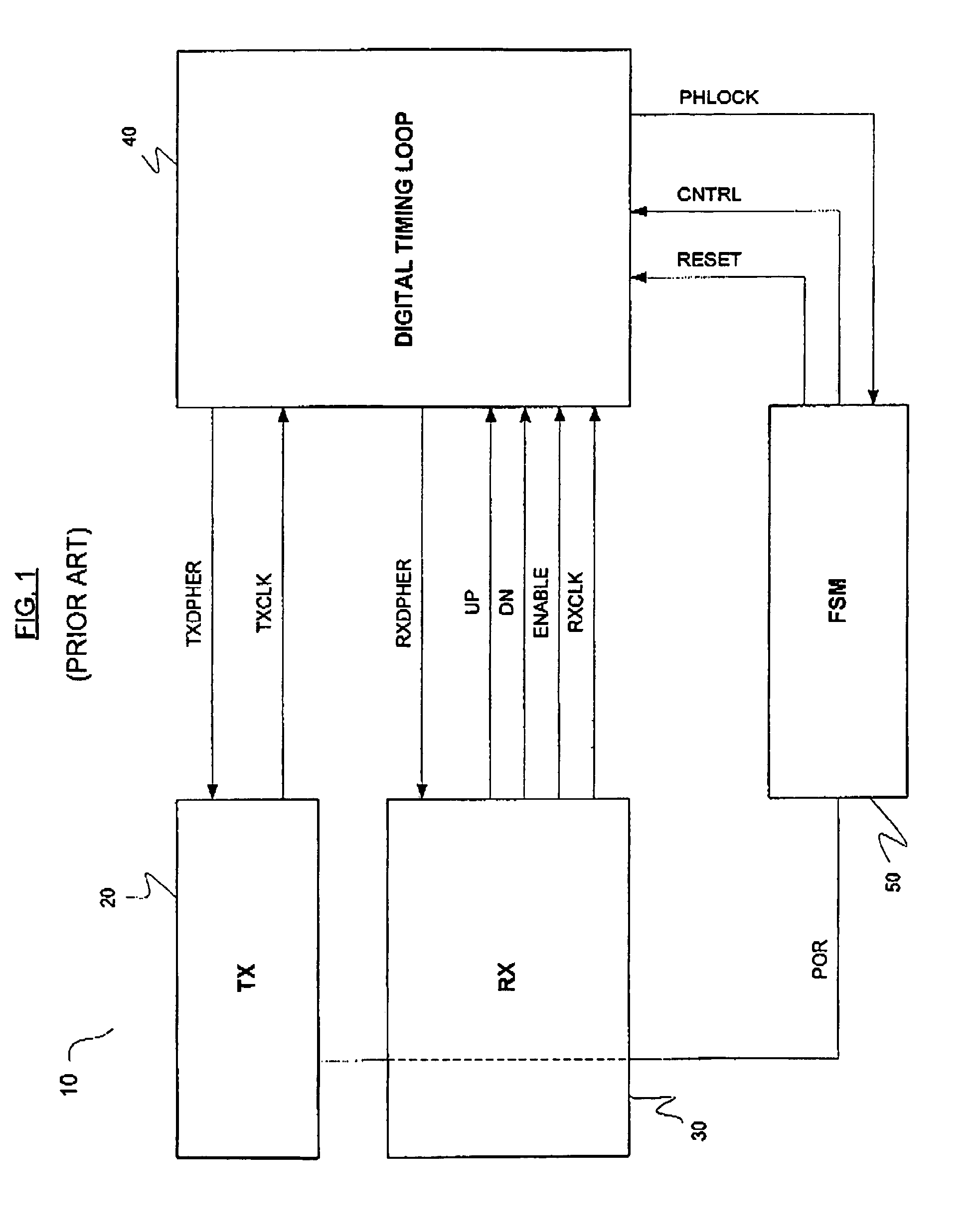
FIELD OF THE INVENTION[0001]The present invention generally relates to the field of clock data recovery. More specifically, embodiments of the present invention pertain to circuitry, architectures, systems and methods for recovering a high frequency clock signal from a data stream.DISCUSSION OF THE BACKGROUND[0002]FIG. 1 shows a conventional physical layer transceiver 10 (or PHY device), configured to operate in a storage network. Transceiver 10 generally comprises a transmitter 20, a receiver 30, a digital timing loop 40 and a finite state machine 50. Digital timing loop 40 receives a digital receiver clock signal RXCLK from receiver 30 and (optionally) a digital transmitter clock signal TXCLK from transmitter 20, and outputs multi-bit adjustment / control signals TXDPHER and RXDPHER to transmitter 20 and receiver 30, respectively. In one embodiment, digital clock signal TXCLK has a frequency about double that of digital clock signal RXCLK. Digital timing loop 40 also receives a cont...

Claims


Application Information

Patent Timeline
Patent Type & Authority Patents(United States)
IPC IPC(8): H03D3/24
CPCH03L7/0807H03L7/093H03L7/0891
Inventor WU, LEISUTIOSO, HENRI
Owner MARVELL ASIA PTE LTD
Learn More