Driving IC of an active matrix electroluminescence device

a technology of active matrix and driving circuit, which is applied in the direction of static indicating devices, instruments, etc., can solve the problems of increasing power consumption, difficult to display gray and obtain uniform picture images, and difficult to adjust voltage intensity according to transmittivity, so as to improve the packing density of the integrated circuit (ic) for driving current.

Inactive Publication Date: 2005-09-13
LG DISPLAY CO LTD
View PDF2 Cites 35 Cited by
  • Summary
  • Abstract
  • Description
  • Claims
  • Application Information

AI Technical Summary

Benefits of technology

[0019]An advantage of the present invention is to provide a driving circuit of an AMELD that can control an output current value according to red, green and blue (R / G / B) channels by receiving a digital signal of n bits, thereby improving packing density of an integrated circuit (IC) for driving current.
[0020]Additional advantages and features of the invention will be set forth in part in the description which follows and in part will become apparent to those having ordinary skill in the art upon examination of the following or may be learned from practice of the invention. The objectives and other advantages of the invention may be realized and attained by the structure particularly pointed out in the written description and claims hereof as well as the appended drawings.
[0021]To achieve these advantages and other advantages and in accordance with the purpose of the invention, as embodied and broadly described herein, in a driving circuit of an AMELD having data and gate drivers that respectively transmit a data signal and a scan signal to each pixel region, the data driver includes a latch latching a control signal temporarily stored, and a plurality of digital to analog converters (DAC) outputting a reference current of a certain level as a data signal according to R / G / B channels by the control signal latched.
[0022]That is, n number of reference current values temporarily set are selectively turned on according to digital signals of n bits for displaying gray desired. Also, two voltage terminals are formed, in which one has a constant voltage value, and the other has a voltage value that is changed according to R / G / B channels. Therefore, it is possible to adjust output voltage terminal according to R / G / B colors.
[0023]It is to be understood that both the foregoing general description and the following detailed description of the present invention are exemplary and explanatory and are intended to provide further explanation of the invention as claimed.

Problems solved by technology

If the threshold voltage is high, the voltage intensity applied to the liquid crystal must be increased, thereby increasing power consumption.
In this case, it is hard to adjust the voltage intensity according to the transmittivity.
Therefore, it is difficult to display gray and to obtain uniformity of the picture images.

Method used


Image

  • Driving IC of an active matrix electroluminescence device
  • Driving IC of an active matrix electroluminescence device
  • Driving IC of an active matrix electroluminescence device

Examples


first and second embodiments

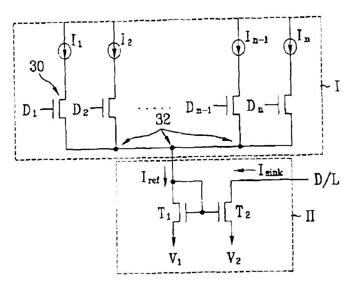
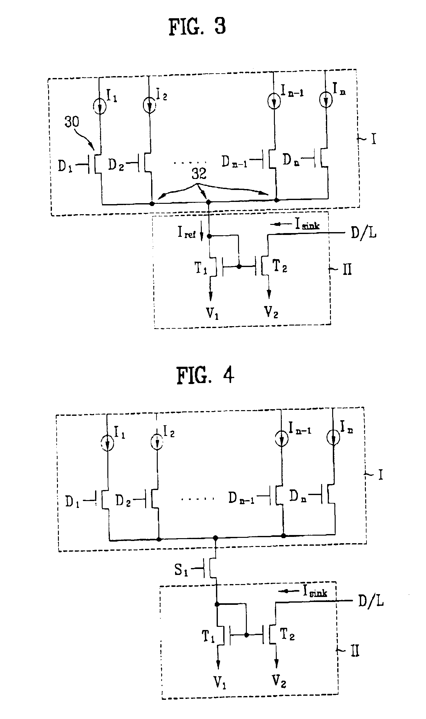
[0048]FIG. 3 illustrates a circuit diagram of a driving circuit in an AMELD according to the first embodiment of the present invention. FIG. 4 illustrates a circuit diagram of a driving circuit in an AMELD according to the second embodiment of the present invention.

[0049]In the driving circuit of the AMELD according to the first embodiment of the present invention, the driving circuit includes a reference current output unit I and a sink current controller II.

[0050]In the reference current output unit I, a plurality reference current sources I1 to In are temporarily combined, and then a reference current Iref of a certain level is output. In the sink current controller II, a level of a sink current can be controlled by receiving the reference current Iref of the certain level output from the reference current output unit.

[0051]The reference current output unit I includes a plurality of switching devices 30. Various currents I1 to In of different levels are applied to input terminals...

third and fourth embodiments

[0058]FIG. 5 illustrates a circuit diagram of a driving circuit of an AMELD according to the third embodiment of the present invention. FIG. 6 illustrates a circuit diagram of a driving circuit of an AMELD according to the fourth embodiment of the present invention.

[0059]A driving circuit of the AMELD according to the third embodiment of the present invention includes a reference current output unit I and a sink current controller II.

[0060]The reference current output unit I includes a plurality of switching devices 50. Various currents I1 to In of different levels are applied to input terminals of the switching devices, and output terminals of the currents are connected to one another. An output level in the output terminals 52, which are connected to one another, is determined by control signals D1 to Dn.

[0061]In the present embodiment, the switching device is a TFT.

[0062]The sink current controller II includes a first voltage terminal V1, a first transistor T1, a fixed resistance...

fifth and eighth embodiments

[0068]FIG. 7 illustrates a circuit diagram of a driving circuit in an AMELD according to the fifth embodiment of the present invention.

[0069]As shown in FIG. 7, the driving circuit of the AMELD includes a reference current output unit I and a sink current controller II.

[0070]The reference current output unit I includes a plurality of switching devices 70. Various currents I1 . . . In of different levels are applied to input terminals of the switching devices 70. Then an output level in output terminals 72, which are connected to one another, is determined by control signals D1 to Dn.

[0071]In the present embodiment, the switching device is a thin film transistor (TFT).

[0072]The sink current controller II includes a first voltage terminal V1, a variable resistance RR, a first transistor T1, a fixed resistance Rs, a second transistor T2, and a third transistor T3. The transistors T1, T2 and T3, are, for example, thin film transistors. At this time, the variable resistance RR is connect...


PUM


Abstract

A driving circuit for an active matrix electroluminescence device (AMELD) can control an output current value according to R/G/B channels by receiving a digital signal of n bits. In the driving circuit of the AMELD having data and gate drivers that respectively transmit a data signal and a scan signal to each pixel region, the data driver includes a latch for latching a control signal temporarily stored, and a plurality of digital to analog converters (DAC) for outputting a reference current of a certain level as a data signal according to R/G/B channels is latched by the control signal.

Description

[0001]This application claims the benefit of the Korean Application No. P2000-077083 filed on Dec. 15, 2000, which is hereby incorporated by reference as if fully set forth herein.BACKGROUND OF THE INVENTION[0002]1. Field of the Invention[0003]The present invention relates to a driving circuit of a display device, and more particularly, to a driving circuit of an active matrix electroluminescence device (AMELD) driven by digital signals.[0004]2. Discussion of the Related Art[0005]An AMELD emits light by electroluminescence. The AMELD is manufactured by forming electrodes of matrix type at both surfaces of a flat shaped luminescent layer. The AMELD includes a picture display unit and a driving circuit unit.[0006]The AMELD has characteristics such as wide viewing angle, rapid response time, high contrast, low voltage driving, low power consumption, thinness and lightness in weight. Furthermore, the AMELD can display various colors, so that the AMELD has been attractive as a new genera...

Claims


Application Information

Patent Timeline
Patent Type & Authority Patents(United States)
IPC IPC(8): G09G3/30G09G3/20
CPCG09G3/30G09G2300/08G09G2310/027
Inventor BAE, SUNG JOONLEE, HAN SANGPARK, JOON KYU
Owner LG DISPLAY CO LTD
Why Eureka
Try Eureka