Magnetic head having a magnetic recording element including a pair of connected yoke films and magnetic pole film to form a magnetic gap

Inactive Publication Date: 2005-09-13
FUJIFILM BUSINESS INNOVATION CORP
View PDF2 Cites 2 Cited by
  • Summary
  • Abstract
  • Description
  • Claims
  • Application Information

AI Technical Summary

Benefits of technology

[0009]The invention is to provide a magnetic head attaining high speed and high density recording, a magnetic disk unit using the magnetic head and a process for producing a magnetic head that is excellent in reproducibility and is relatively inexpensive.

Problems solved by technology

However, due to the superparamagnetic effect and the difficulty in reducing the gap width of the magnetic head, recording density of the conventional HDD is approaching its limitation.
Rather, a reduction of the width of the magnetic pole of the magnetic circuit has become a serious problem.
According to the conventional production process of a magnetic head, however, when the width W of the magnetic pole 46′ is decreased to 50 to 60 nm, the thickness T of the magnetic pole 46′ is further necessarily increased to prevent magnetic saturation around the magnetic pole 46′, but a thick magnetic film is difficult to be subjected to microfabrication and results in poor reproducibility.
In the method shown in FIG. 7E, it is difficult to form a gap of 0.1 μm or less in a stable manner, and it is also difficult to embed a metal for the magnetic pole in the gap.

Method used


Image

  • Magnetic head having a magnetic recording element including a pair of connected yoke films and magnetic pole film to form a magnetic gap
  • Magnetic head having a magnetic recording element including a pair of connected yoke films and magnetic pole film to form a magnetic gap
  • Magnetic head having a magnetic recording element including a pair of connected yoke films and magnetic pole film to form a magnetic gap

Examples


first embodiment

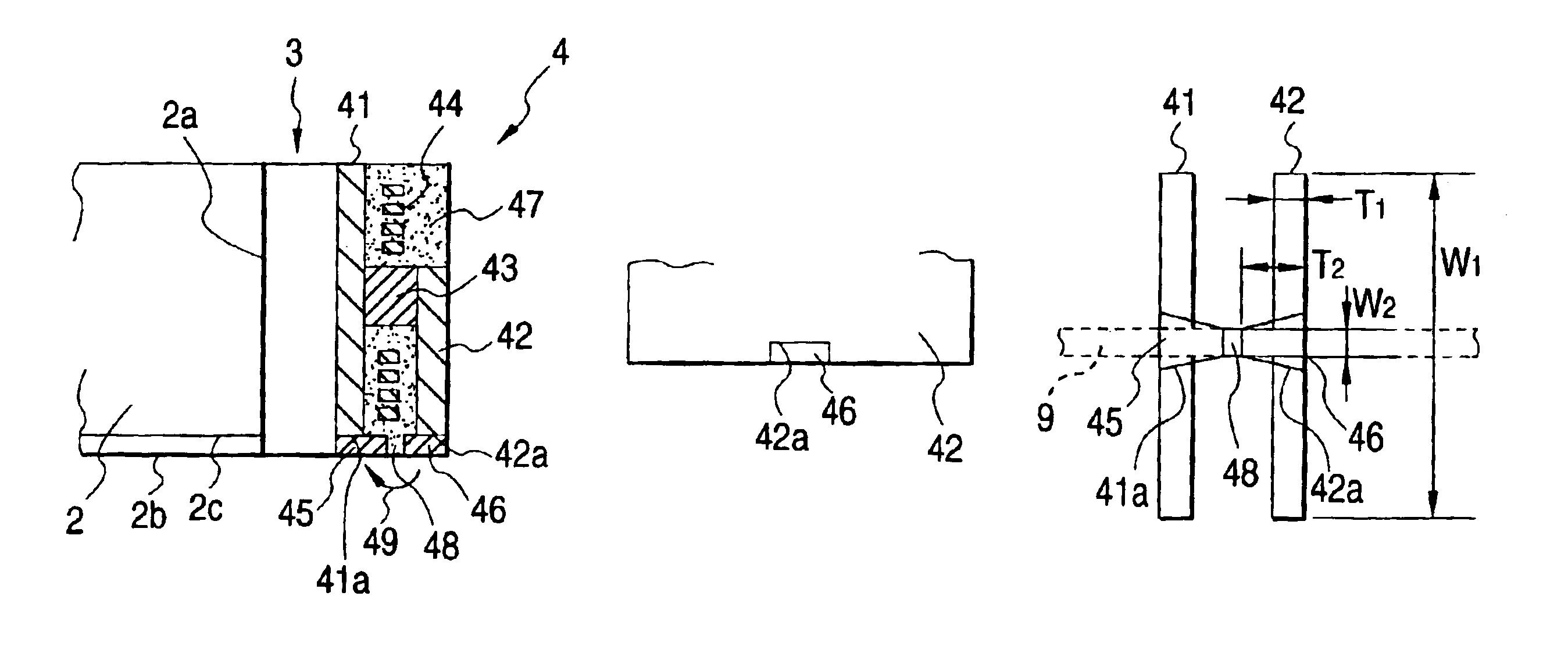
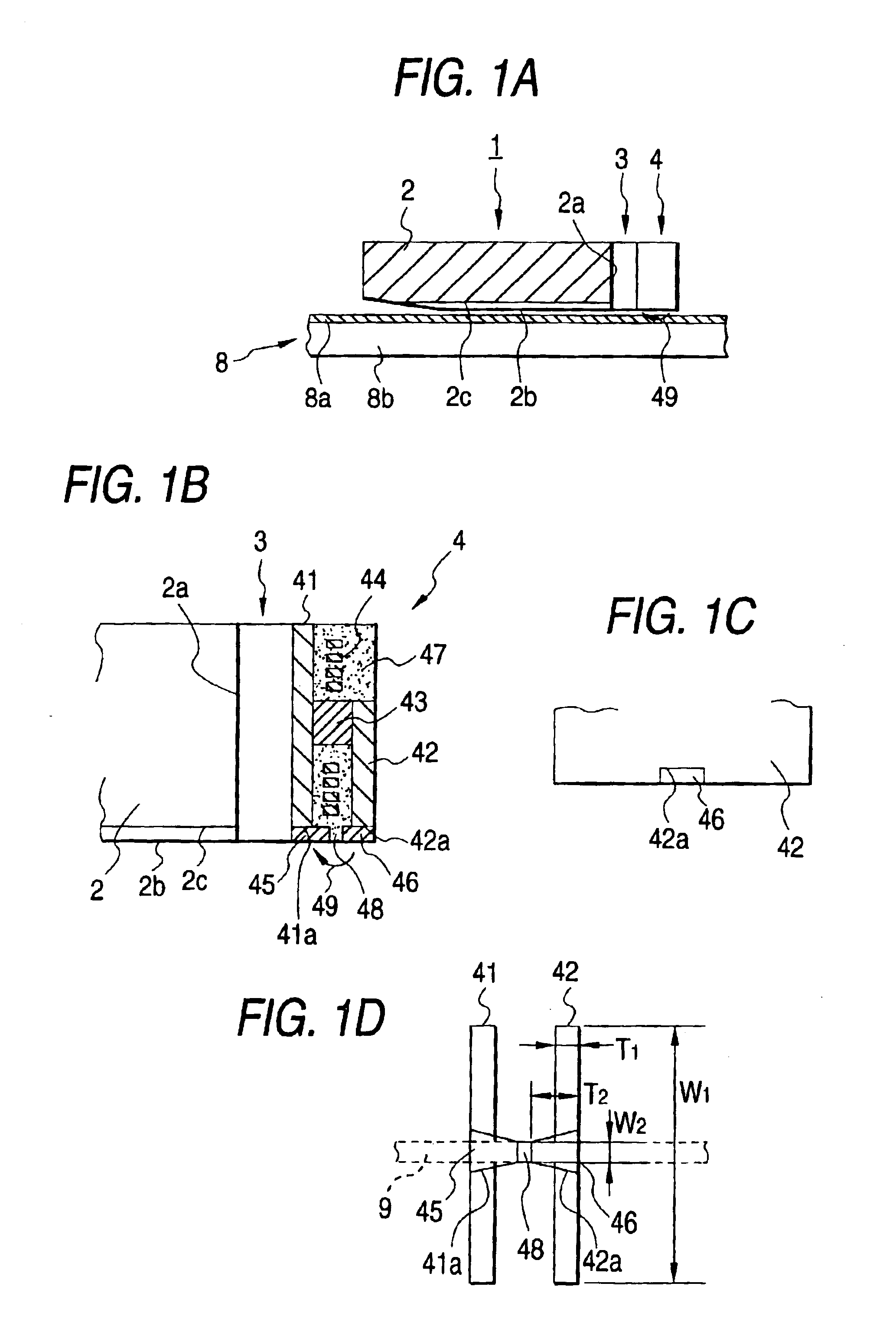
[0031]FIGS. 1A to 1D show a main part of a magnetic head relating to the invention. As shown in FIG. 1A, a magnetic head 1 has a magneto-resistive sensor 3 and a magnetic recording transducer 4 consecutively piled on a back end surface 2a of a flying slider 2, and the head flies above a magnetic recording layer 8a formed on a substrate 8b of a magnetic disk 8 by a flying surface 2b having a concave part 2c of the flying slider 2. The head records information in the magnetic recording layer 8a with a magnetic field 49 leaked from the magnetic recording transducer 4, and reproduces information with the magneto-resistive sensor 3.

[0032]As shown in FIGS. 1B, 1C and 1D, the magnetic recording transducer 4 is formed in the following manner. A lower yoke 41 formed functioning as a magnetic shield film, a dielectric film 47 as an insulating film supporting a thin film coil 44, and an upper yoke 42 constituting a magnetic circuit by connecting at a back end of the lower yoke 41 through a con...

second embodiment

[0041]FIG. 3 shows a main part of a magnetic head according to the invention. The magnetic head has plural magnetic gaps 48a and 48b, which are formed with two magnetic poles 46a and 46b facing the magnetic pole 45, wherein one magnetic pole 45 is commonly used. Two thin film coils (not shown in the figure) are formed between a yoke 41 and yokes 42a and 42b, and the coils can drive respective magnetic circuits independently from each other. Two magneto-resistive sensors are formed at positions corresponding to the magnetic gaps 48a and 48b.

[0042]FIGS. 4A and 4B show two magneto-resistive sensors in the second embodiment. In the magneto-resistive sensor, the spin valve films 31a and 31b are separated into two by an electrode 32a, and signal detection can be carried out independently from each other from electrodes 32b and 32b′ on both ends. In the figure, numeral 34 denotes a magnetic shield film, and 33a and 33b denote insulating films. According to the structure, the plural magnet...

fourth embodiment

[0046] such a magnetic recording transducer 4 can be used that has a low magneto-resistance and a strong leakage magnetic field with minute width and length, and therefore, a magnetic disk unit with high recording and reproduction speed and a high recording density can be provided.

[0047]The thin film coil may be wound on an axis along a direction perpendicular to the sliding direction of the flying slider. Furthermore, a magnetic recording transducer may be deposited on the back end surface of the flying slider, and a magneto-resistive sensor is deposited further thereon.

[0048]As described in the foregoing, according to the invention, because the shape of the surface of the magnetic pole facing the magnetic recording medium is determined by the working pattern of the thin film, a magnetic pole having a high aspect ratio can be formed, and a magnetic head can be produced by a relatively inexpensive production process, whereby high speed and high density recording can be attained. Fur...


PUM


Abstract

A process for producing a magnetic head attaining high speed and high density recording, excellent in reproducibility and relatively inexpensive is provided as well as a magnetic head and a magnetic disk unit. A lower yoke film, an insulating film supporting a thin film coil and an upper yoke film connected at a back end thereof to a back end of the lower yoke film are consecutively piled on a back end surface of a flying slider, and a magnetic pole films and a deposited at a tip end of at least one of the lower yoke film and the upper yoke film, so as to form a magnetic gap. The gap of the surface of the magnetic pole facing a magnetic recording medium is determined by the working pattern of the thin film; therefore, a magnetic pole having a high aspect ratio can be easily produced.

Description

BACKGROUND OF THE INVENTION[0001]1. Field of the Invention[0002]The present invention relates to a process for producing a magnetic head that records information on a magnetic disk with a magnetic field, a magnetic head and a magnetic disk unit, and more particularly, it relates to a magnetic head attaining high speed and high density recording, a magnetic disk unit using the magnetic head and a process for producing a magnetic head that is excellent in reproducibility and is relatively inexpensive.[0003]2. Description of the Related Art[0004]The recording density of hard disk recording units (hard disk drive, commonly abbreviated as HDD) is increasing by 100% per year in recent years, and it is reaching 100 Gb / (inch)2 in an experimental phase. However, due to the superparamagnetic effect and the difficulty in reducing the gap width of the magnetic head, recording density of the conventional HDD is approaching its limitation. As a measure against the superparamagnetic effect, a perp...

Claims


Application Information

Patent Timeline
IPC IPC(8): G11B5/147G11B5/31G11B5/60
CPCG11B5/147
Inventor UEYANAGI, KIICHI
Owner FUJIFILM BUSINESS INNOVATION CORP
Why Eureka
Try Eureka