
Ultrasonic length measuring apparatus and method for coordinate input

Inactive Publication Date: 2005-09-13
FUJITSU LTD
View PDF8 Cites 27 Cited by
  • Summary
  • Abstract
  • Description
  • Claims
  • Application Information

AI Technical Summary

Benefits of technology

[0009]The present invention provides an ultrasonic length measuring apparatus and method enabling an extremely high-precision length measurement with a relatively simple configuration.
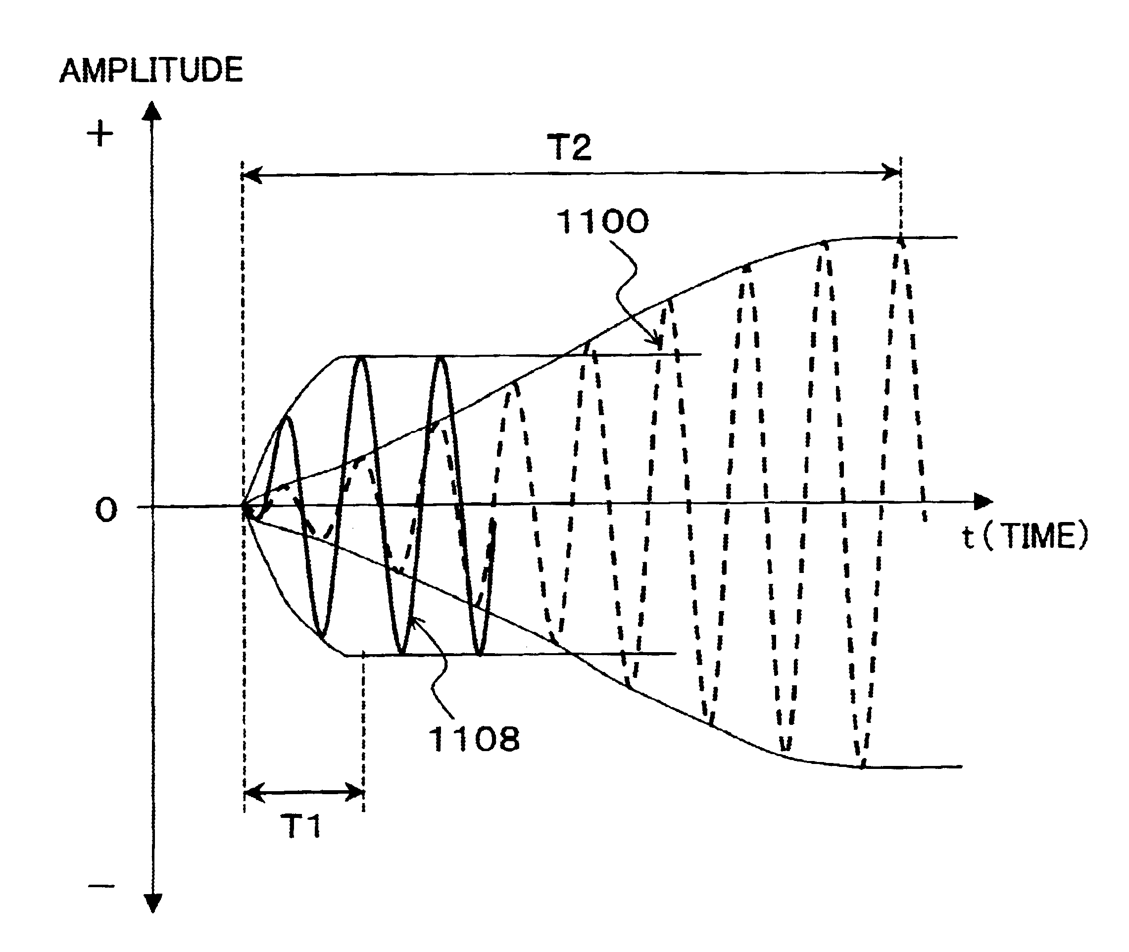
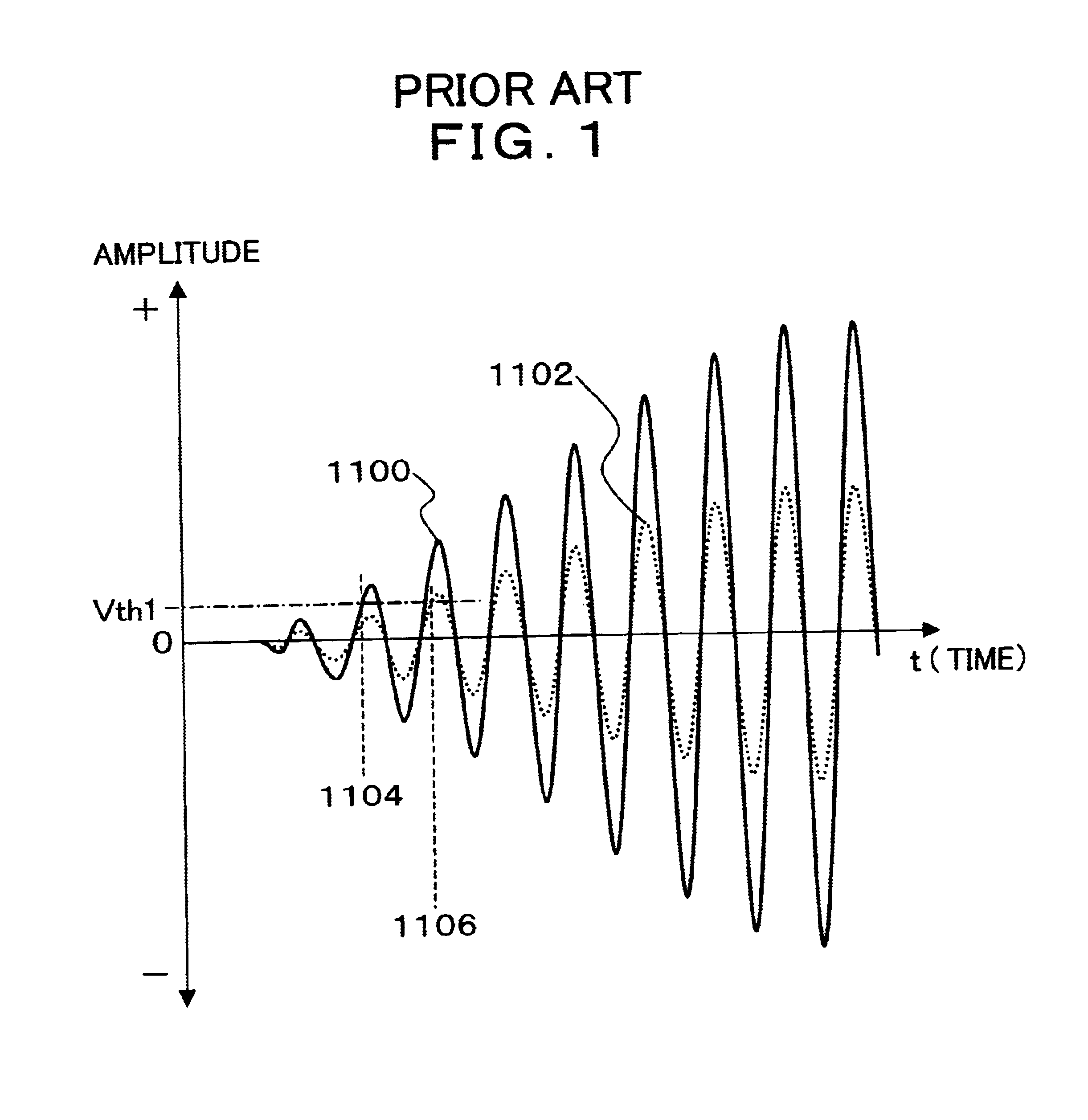
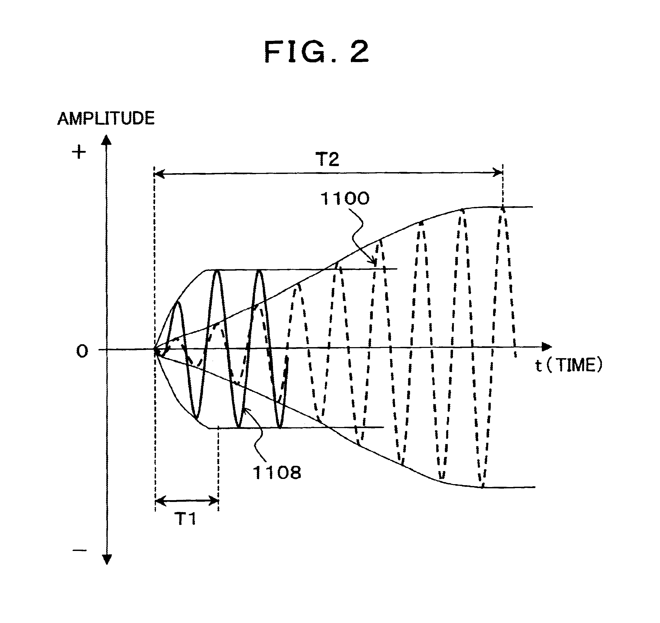
[0010]According to a first aspect of the present invention there is provided an ultrasonic length measuring apparatus comprising a transmission unit for transmitting an ultrasonic wave; at least one receiving unit (ultrasonic sensor) for receiving an ultrasonic wave and converting it into an electric signal; a timing detection unit for measuring the number of times of the crossing of the waveform of the received ultrasonic wave signal from the receiving unit over a predetermined threshold value and for detecting a crossing timing after predetermined times from a crossing point of a first crossing; a time measuring unit for measuring the time period from the start of transmission of the ultrasonic wave by the transmission unit to the crossing timing detected; and a length measuring unit for calculating a length based on the time measured. As a result of inventors' active consideration, the resolution of the measurement of the arriving time using the received waveform of the ultrasonic wave depends on the inclination of the waveform crossing the threshold value and the resolution obtained becomes higher as the amplitude becomes larger because the inclination becomes steeper. That is, the dispersion of the timing for crossing the threshold value becomes smaller as the amplitude becomes larger. Therefore, the invention improves the measurement precision of the propagation time by detecting the crossing timing with a wave having a large amplitude that has a steep inclination of its waveform for crossing the threshold.
[0011]According to a second aspect of the present invention there is provided an ultrasonic length measuring apparatus comprising a transmission unit for transmitting an ultrasonic wave; at least one receiving unit for an ultrasonic wave and converting it into an electric signal; a timing detection unit for measuring the number of times of the crossing of the waveform of the received ultrasonic wave signal from the receiving unit over a predetermined threshold value and for detecting each crossing timing for predetermined times from the crossing point after predetermined times from the crossing point of first crossing; a time measuring unit for measuring the time period from the start of transmission of the ultrasonic wave by the transmission unit to the each crossing timing detected, and obtaining the arithmetic mean of each time measured; and a length measuring unit for calculating a length based on the time obtained as the arithmetic mean. In this case, it is possible to further improve the effective temporal resolution by obtaining the arithmetic mean of a plurality of the crossing timing when the inclination of the waveform crossing the threshold becomes steep.

Problems solved by technology

The magnetic-type or pressure-sensitive-type tablet has an excellent characteristic as above but the area for writing operation is limited within the sensor plane attached to it.
If the area for writing is extended, a larger apparatus is necessary as an apparatus constituting the sensor plane and, in this case, the cost of the sensor plane unit increases as well as a large space for accommodating the sensor plane unit is necessary.
As a result, an error corresponding to one wavelength is produced.
In the case of the method utilizing the envelope, the wave crossing the threshold is not mistaken like in the case utilizing directly the waveform of an ultrasonic wave but the temporal resolution can not made high.
Especially, because the process necessary for the electronization if the hand-written characters are read out by an image scanner and it is inconvenient to carry if a touch-panel or a tablet is employed, it is desirable to be able to input the hand-written characters easily as electronized data.
However, when such a conventional technique employing triangulation is used, an area being a blind spot is created in a portion of the sheet of paper and the problems that inputting coordinates becomes impossible or the resolution becomes degraded consequently even if the input is possible occur.
In addition, problems of larger size of the apparatus and increased cost occur.

Method used


Image

  • Ultrasonic length measuring apparatus and method for coordinate input
  • Ultrasonic length measuring apparatus and method for coordinate input
  • Ultrasonic length measuring apparatus and method for coordinate input

Examples


embodiment 1

[0088]FIGS. 18A and 18B illustrate an example of the arrangement of the receiver 101. This arrangement is remarkably characterized in that the receiver 101 can be arranged on a corner of the sheet to eliminate any blind spot from the built-in ultrasonic receiver by composing the receiver 101 compactly. That is, the receiver 101 is positioned on a upper corner either on the left or right on the sheet face as its position and it is preferable that the receiver 101 is positioned on the upper-right corner as shown in FIG. 18A when the user is right-handed. This is for preventing to interrupt the ultrasonic wave and the infrared ray sent out from the pen with user's left hand when the left hand holds the sheet. In contrast, for a left-handed user, the receiver 101 is positioned on the upper-left corner, as shown in FIG. 18B, while using the apparatus. Now, the characteristics of this embodiment 1 will be mainly described.

[0089]As shown in FIGS. 19A to 19C, the receiver 101 has a configur...

first embodiment

[0107]In the invention for solving the problem of mis-detection due to the sound of collision, as shown in FIG. 37, a delay circuit 211 is provided between the writing detection mechanism 201, and the synchronized circuit 203 and the ultrasonic wave drive circuit 205. The sound of collision in problem is generated at the initial point of each stroke in the writing action by the operator, i.e., it is generated at the first moment of contacting of the pen tip of the pen-shaped mover 210 with the face for writing. Then, in the embodiment, as shown in FIGS. 38A to 38C, it has a configuration in which, by providing a predetermined delay T by the delay circuit 211 after the writing has been detected at the writing detection mechanism 201, an intermittent ultrasonic wave transmission is implemented through the timer 202 by the ultrasonic wave drive circuit 205 after the time T has passed. Because a waiting time is provided after the writing detection until the sound of collision and its ec...

second embodiment

[0108]Next, the invention for preventing the mis-detection due to the sound of collision will be described. It is possible to eliminate apparently the effect of the sound of collision if the operator is let not notice the effect even when the operator is under the effect of the sound of collision. That is, it is preferable to have a configuration in which the end of each stroke of the writing action of the pen-shaped mover by the operator is detected and, the first coordinate detection data of the next stroke starting immediately after this is not used (is ignored). This is an approach utilizing the fact that the sound of collision in problem is generated only at the moment of each stroke of the writing action. In this embodiment, the detection of the end of a stroke is conducted by, more specifically, for example, detecting a transmission repetition rate of the ultrasonic wave transmitted intermittently at a constant period and judging if the period of the repetition rate (approxim...


PUM


Abstract

An ultrasonic length measuring apparatus measures the number of times a waveform of an ultrasonic wave signal crosses a threshold value, detects the crossing timing at, for example, a waveform having a maximal amplitude after a predetermined number of times counting from a first crossing point, measures the time period from the transmission start of the ultrasonic wave by the transmission unit to the detected crossing timing and calculates the length based on the time measured. A coordinate inputting apparatus includes a pen for transmitting an ultrasonic wave and a coordinate inputting apparatus for inputting coordinate positions of the pen based on a propagation time of the ultrasonic wave transmitted by the pen and received by a plurality of ultrasonic wave receivers. The receiver includes at least a pair of ultrasonic receivers for receiving the ultrasonic wave transmitted by the pen.

Description

BACKGROUND OF THE INVENTION[0001]1. Field of the Invention[0002]The present invention relates generally to an ultrasonic length measuring apparatus and method for measuring the length by counting the propagation time of ultrasonic waves and, more particularly, to an ultrasonic length measuring apparatus and method for coordinate inputting, as character data or graphic data, tracks created by hand-writing characters or figures on a sheet of paper with a dedicated pen.[0003]2. Description of the Related Arts[0004]Mice, trackballs and magnetic-type or pressure-sensitive-type tablets etc. are known as coordinate inputting apparatuses (pointing devices) for inputting the coordinate information to the computer. Among these, the magnetic-type or pressure-sensitive-type tablets are excellent in terms of usability and precision. This is a pointing apparatus with which, when a magnetic-type or pressure-sensitive-type sensor plane is traced with a pen-type mover, the coordinate positions on th...

Claims


Application Information

Patent Timeline
IPC IPC(8): G06F3/033G01S15/08G06F3/0354G06F3/043
CPCG06F3/03545G06F3/0433G01S15/08
Inventor HAMA, SOICHISEKIGUCHI, HIDENORIFUJII, AKIRA
Owner FUJITSU LTD
Learn More