Differential pressure gauge for cryogenic fluids which selects a density value based on pressure measurement

a technology of density value and pressure measurement, which is applied in the direction of mechanical measuring arrangement, instrumentation, discharging method of container, etc., can solve the problems of reducing the volume of liquid in the container, reducing the volume of liquid in the tank, and determining the volume of liquid in the container is more difficult, so as to achieve the effect of minimizing the site visit of supply trucks

Inactive Publication Date: 2005-09-13
U S BANK TRUST CO NAT ASSOC AS THE NOTES COLLATERAL AGENT
View PDF1 Cites 19 Cited by
  • Summary
  • Abstract
  • Description
  • Claims
  • Application Information

AI Technical Summary

Benefits of technology

[0010]To determine a liquid volume present at a particular instant, the differential pressure sensor sends an analog signal, corresponding to a differential pressure, to the onboard computer contained within the gauge. The analog signal is converted to a digital signal. The gauge analyzes this digital signal along with the initial input information from the user, and a signal from a pressure sensor using stored formulas and properties to calculate a liquid volume. The results are displayed on the device, or may be transmitted via telemetry to a remote device of the user's choosing. Because a visit by a human operator to a site is now not needed just to ascertain liquid volume, site visits by supply trucks can be minimized and can be automatically triggered by the gauge detecting that a tank's liquid volume has fallen below a predetermined level.

Problems solved by technology

Unique problems are encountered in handling and storing cryogenic liquids because the liquids undergo density changes at various storage pressures.
Even though the tank is insulated, heat will enter the tank, causing the liquid cryogen to slowly vaporize to a gas and, as a result, causing the volume of liquid in the tank to diminish.
Determining the volume of the liquid in the container is more difficult, however.
Such calibration charts are awkward to use, and separate charts are required for different combinations of the factors listed above.
This prevents efficient on-site monitoring of the liquid volume.

Method used


Image

  • Differential pressure gauge for cryogenic fluids which selects a density value based on pressure measurement
  • Differential pressure gauge for cryogenic fluids which selects a density value based on pressure measurement
  • Differential pressure gauge for cryogenic fluids which selects a density value based on pressure measurement

Examples


Embodiment Construction

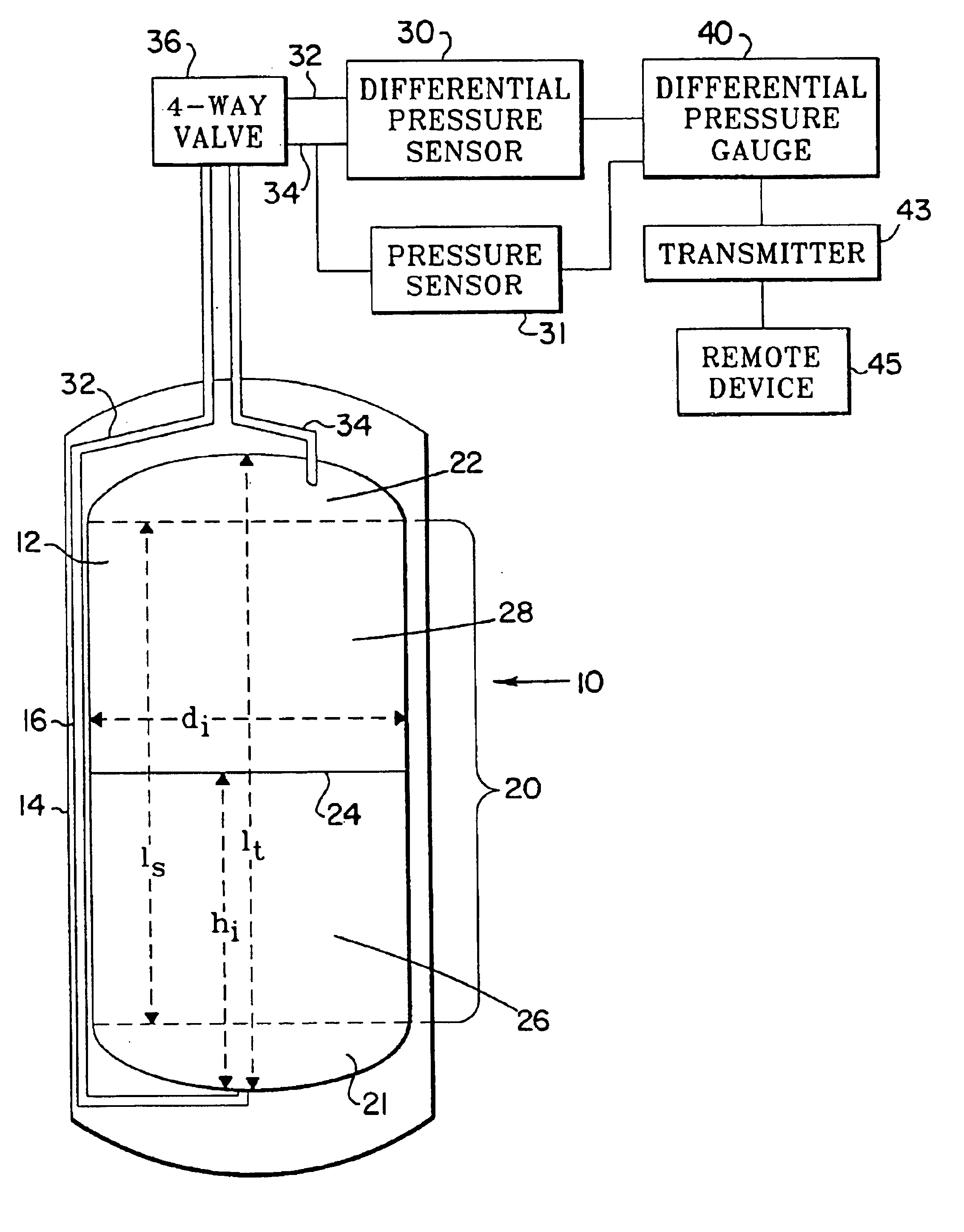
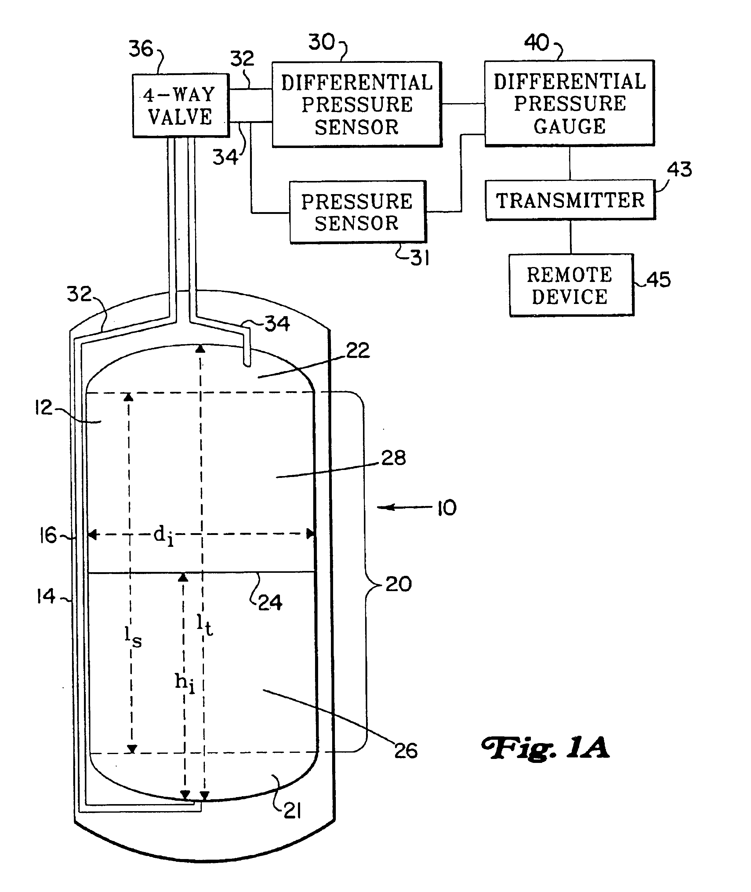
[0027]FIG. 1 shows a cryogenic storage vessel fitted with the differential pressure gauge of the present invention, the vessel being indicated generally at 10. Vessel 10 contains an inner tank 12 for holding cryogenic liquid. The tank 12 comprises a shell portion 20 and bottom and top convex end portions 21, 22. The top of the liquid level is shown at 24, and the height of the inner liquid is indicated by hi. The tank has overall tank length lt and inner diameter di. An outer jacket 14 surrounds inner tank 12, forming an insulation chamber 16 between the jacket 14 and tank 12. The insulation chamber 16 is filled with an insulation material (not shown), and a vacuum is created within chamber 16 to minimize the heat transfer between the external environment and the interior of the tank 12.

[0028]As heat from outside of the vessel 10 transfers into the tank, a portion of the liquid at the bottom of the container will vaporize and move to the top of the container, separating the contents...


PUM


Abstract

A differential pressure gauge for a cryogenic storage tank provides onboard entry, by an operator, of tank dimensions, tank orientation stratification coefficient, and the type of liquid stored within the tank. A differential pressure sensor supplies a signal corresponding to a differential pressure. A pressure sensor supplies a signal corresponding to the head pressure. The gauge uses the information supplied by an operator, combined with stored formulas and liquid characteristics, to perform real-time liquid volume computations. The liquid volume may be displayed on the gauge itself or may be transmitted via telemetry to an external device.

Description

RELATED APPLICATION[0001]This application is a division of U.S. patent application Ser. No. 09 / 923,636 filed on Aug. 7, 2001 now U.S. Pat. No. 6,782,339, which in turn is a continuation-in-part of commonly assigned U.S. patent application Ser. No. 09 / 628,621 entitled DIFFERENTIAL PRESSURE GAUGE FOR CRYOGENIC FLUIDS filed Jul. 31, 2000 now U.S. Pat. No. 6,542,848.TECHNICAL FIELD[0002]The invention relates generally to the storage of cryogenic fluids and, more specifically, to an improved differential pressure gauge that performs real-time calculations of liquid volumes so that the gauge is easier to use and can be configured to various models of cryogenic containers.BACKGROUND OF THE INVENTION[0003]Cryogenic liquids, such as nitrogen, argon, nitrous oxide, oxygen, carbon dioxide, hydrogen, and the like, liquify at extremely cold temperatures. Unique problems are encountered in handling and storing cryogenic liquids because the liquids undergo density changes at various storage pressu...

Claims


Application Information

Patent Timeline
Patent Type & Authority Patents(United States)
IPC IPC(8): F17C13/00F17C13/02G01F23/14G01F22/02G01D7/00
CPCF17C13/025F17C13/028G01F23/14F17C2250/0434Y02E60/321F17C2201/0109F17C2203/0308F17C2203/0391F17C2203/0629F17C2205/0323F17C2221/011F17C2221/012F17C2221/013F17C2221/014F17C2221/016F17C2223/0161F17C2223/033F17C2250/032F17C2250/034F17C2250/036F17C2250/0408F17C2250/0426F17C2250/0447F17C2250/0495F17C2250/0694F17C2270/0171Y02E60/32
Inventor NEESER, TIMOTHYSCHMOECKEL, CHRISTOPHER JON
Owner U S BANK TRUST CO NAT ASSOC AS THE NOTES COLLATERAL AGENT
Why Eureka
Try Eureka