Optical connector

a technology of optical connectors and housings, applied in the field of optical connectors, can solve the problems of increasing noise, increasing time and labor, and difficulty in combining the first housing and the second housing with each other, so as to reduce time and labor and facilitate the insertion of the housing

Inactive Publication Date: 2005-09-20
YAZAKI CORP
View PDF6 Cites 34 Cited by
  • Summary
  • Abstract
  • Description
  • Claims
  • Application Information

AI Technical Summary

Benefits of technology

[0012]An object of this invention is to provide an optical connector which can easily couple housings with each other and reduce the time and labor needed for assembling.
[0020]In this configuration, the first ferrule is movably supported within the first housing along the axial line of the optical fiber cable. The urging means, which is accommodated in the second housing, urges the second ferrule toward the first housing. Therefore, when the first housing and the second housing are coupled with each other, the first ferrule moves along the axial line of the optical fiber, thereby suppressing the force of causing these housings to approach each other.
[0021]Further, the first ferrule is movably supported within the first housing along the axial line of the optical fiber. The urging means for urging the first ferrule is not provided within the first housing. This suppresses the labor required to assemble the first connector.
[0022]When the first housing and the second housing are coupled with each other, the urging means urges the second housing in the direction of leaving the first housing. This prevents the first housing and the second housing from rattling.
[0024]In this configuration, when the outer housing of the second housing is coupled with the first housing, the inner housing is brought into contact with the first ferrule within the first housing. Therefore, even if the coupling / decoupling between the first housing and second housing is repeated, since the first ferrule and the second ferrule are not brought into contact with each other, the abrasion of these ferrules can be prevented.

Problems solved by technology

However, with an increase in the number of auxiliary machines and their circuits in recent years, there is a tendency of increasing the noise occurring when an electric signal is transferred.
This makes it difficult to couple the first housing and the second housing with each other, and hence to connect the optical fiber cables to each other.
Since the first housing and the second housing are provided with the corresponding coil springs, respectively, increased time and labor must be taken, thereby increasing the number of man-hours for assembling the first housing and the second housing.
Therefore, when the coupling and decoupling between these housings are repeated, the ferrules may wear.
The wearing of the ferrules may cause the optical axes of the ferrules to deviate from each other, thereby decreasing the transmission efficiency of the optical signal transmitted by these optical fiber cables.
Further, since the ferrules are brought into contact with each other, in the worst case, the optical fiber cables may be damaged, thereby further reducing the transmission efficiency of the optical signal.

Method used


Image

  • Optical connector
  • Optical connector
  • Optical connector

Examples


Embodiment Construction

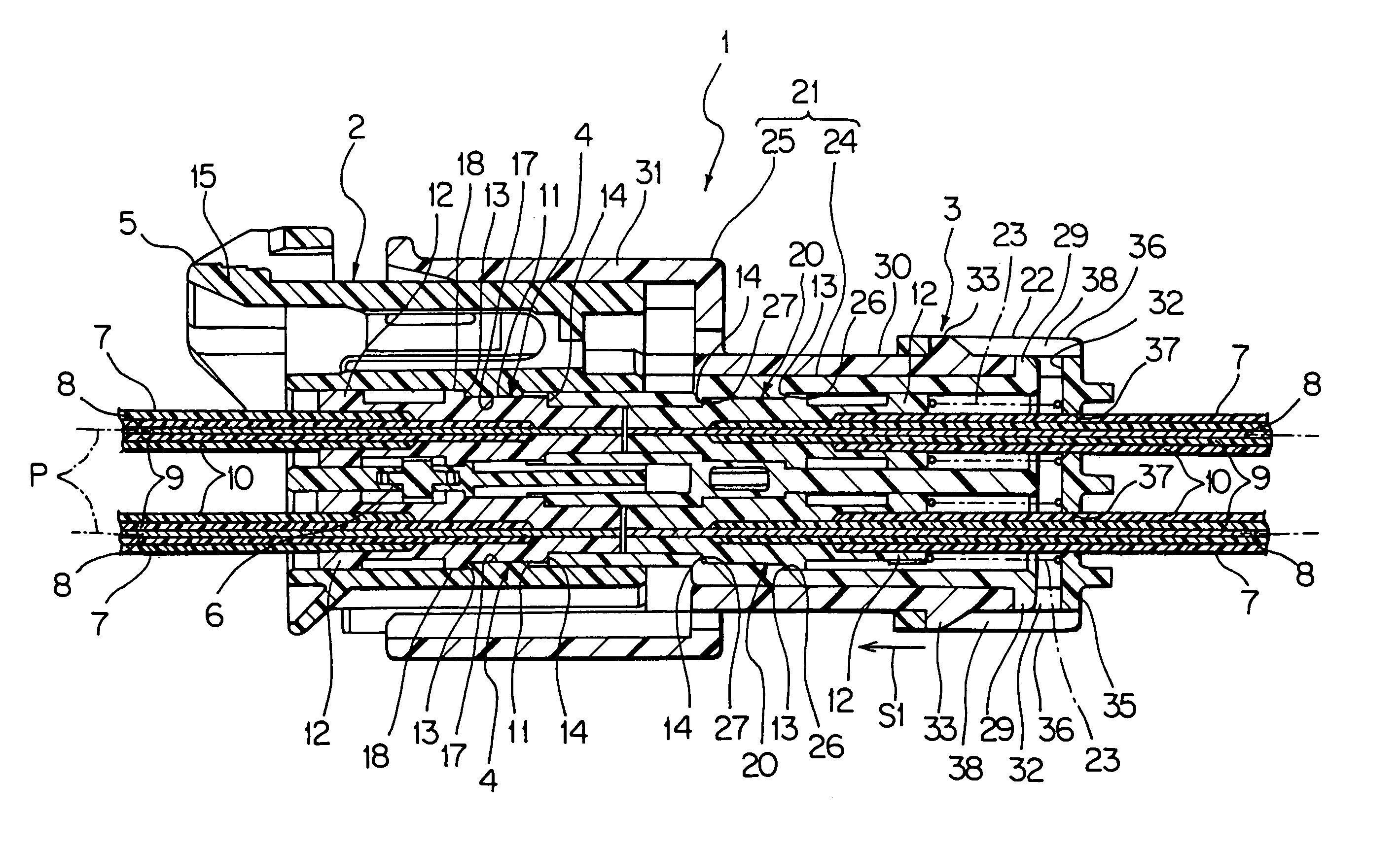
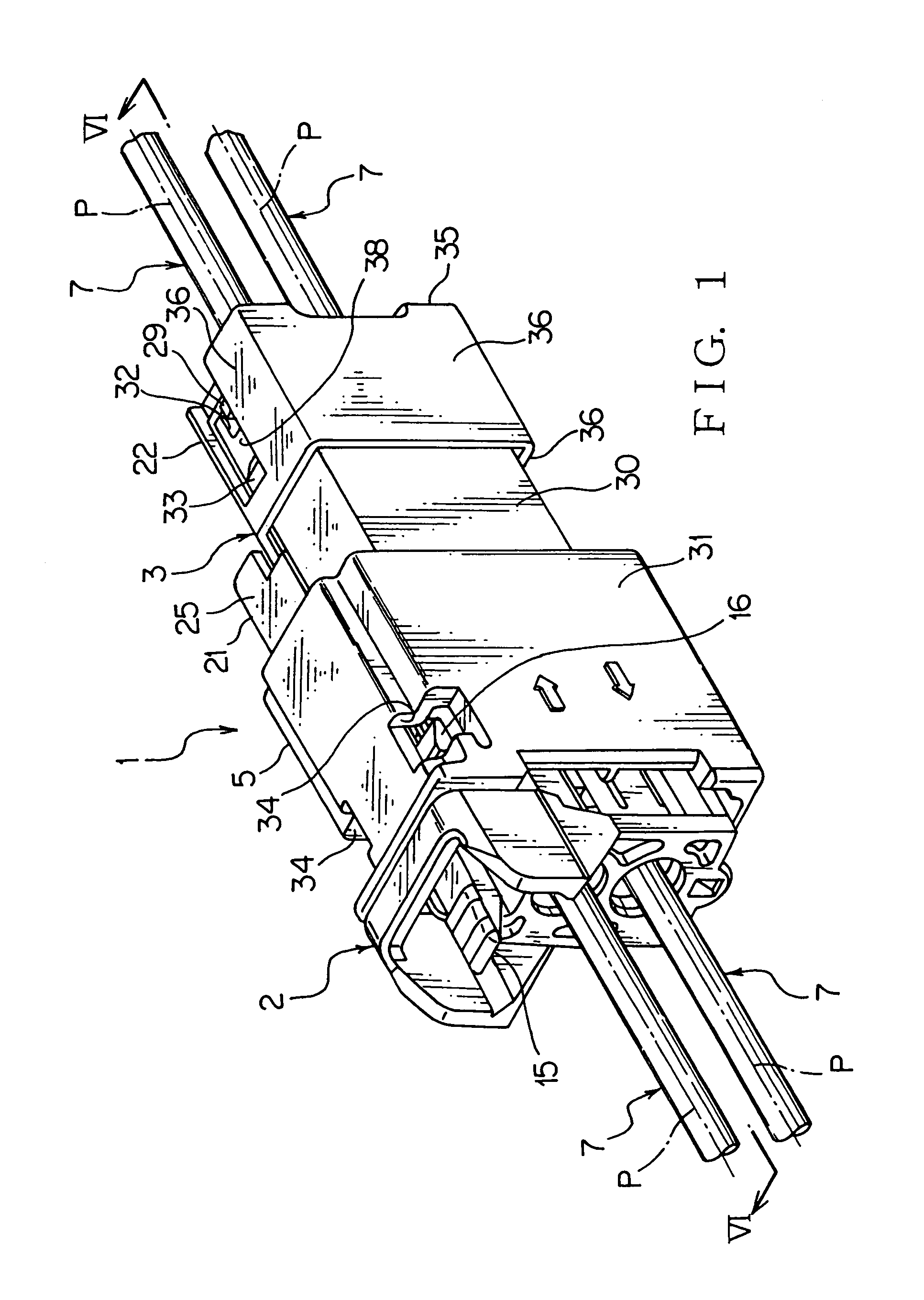
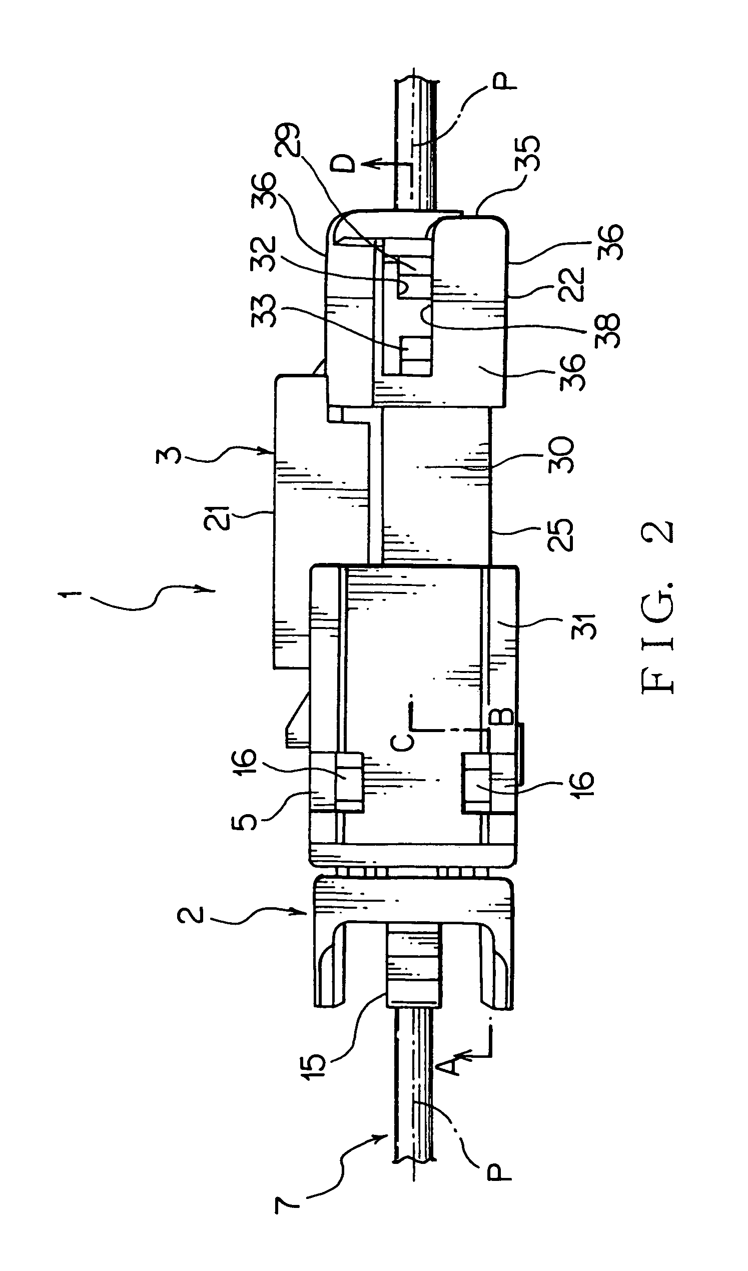
[0036]Now referring to FIGS. 1 to 10, an explanation will be given of an optical connector according to an embodiment of this invention. An optical connector 1 according to the embodiment, as shown in FIGS. 1 to 10, a first connector 2 and a second connector 3 which can be freely coupled and decoupled.

[0037]The above optical connector 1 transmits an optical signal in such a manner that the first connector and the second connector are coupled.

[0038]The first connector 2, as shown in FIGS. 3, 5 to 10, includes a pair of first ferrules 4, a first housing 5 and a spacer 6 (FIGS. 3 and 6 to 10). Each of the first ferrules 4 is provided with an optical fiber cable 7. The optical fiber cable 7, as shown in FIG. 3, includes an optical fiber 8, a first sheath 9 and a second sheath 10. The optical fiber 8 is a well known multi-mode plastic fiber composed of a core and cladding which are formed to have different refraction indices and arranged coaxially.

[0039]The first and the second sheaths 9...


PUM


Abstract

An optical connector 1 includes a first connector 2 and a second connector 3. The first connector 2 includes a first ferrule 4 and a first housing 5. The terminal of an optical fiber 7 is attached to the first ferrule 4. The first housing 5 accommodates the first ferrule 4 so as to be movable along the axial line P of an optical fiber cable 7. The second connector 3 includes a second ferrule 20, a second housing 21 and a coil spring 23. The terminal of another optical fiber cable 7 is attached to the second ferrule 20. The second housing 21 accommodates the second ferrule 20 and the coil spring 23. The coil spring 23 urges the second ferrule 20 toward the first connector 2. Such a configuration provides an optical connector which permits the housings to be easily coupled with each other and suppresses the labor for assembling the connector.

Description

BACKGROUND OF THE INVENTION[0001]1. Field of the Invention[0002]This invention relates to an optical connector for accommodating the terminal of an optical fiber for transmitting an optical signal.[0003]2. Description of the Related Art[0004]Conventionally, a wire harness has been employed for connection of an auxiliary machine of a motor vehicle. However, with an increase in the number of auxiliary machines and their circuits in recent years, there is a tendency of increasing the noise occurring when an electric signal is transferred. In order to suppress the increase in the noise, an optical fiber communication system has been proposed which employs an optical fiber in a part of the wire harness.[0005]The above optical fiber communication system employs various optical connectors in order to convert an optical signal transmitted from an optical fiber cable into an electric signal and vice versa. Further, the optical fiber communication system employs various optical connectors in ...

Claims


Application Information

Patent Timeline
Patent Type & Authority Patents(United States)
IPC IPC(8): G02B6/38
CPCG02B6/3869G02B6/3821G02B6/3878G02B6/3893
Inventor YAMAGUCHI, NOBORU
Owner YAZAKI CORP
Why Eureka
Try Eureka