
CMOS image sensor device and method

a sensor device and image technology, applied in the field of photodiode devices and methods, can solve the problems of high reflection of optical energy, excessive junction leakage of silicium, and optical opaqueness of silicium,

Inactive Publication Date: 2005-09-20
TAIWAN SEMICON MFG CO LTD
View PDF8 Cites 50 Cited by
  • Summary
  • Abstract
  • Description
  • Claims
  • Application Information

AI Technical Summary

Benefits of technology

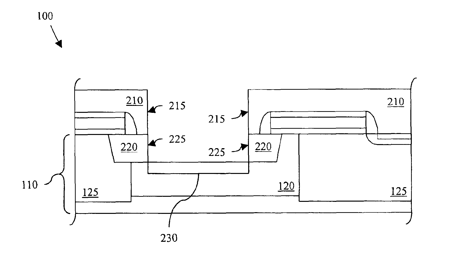
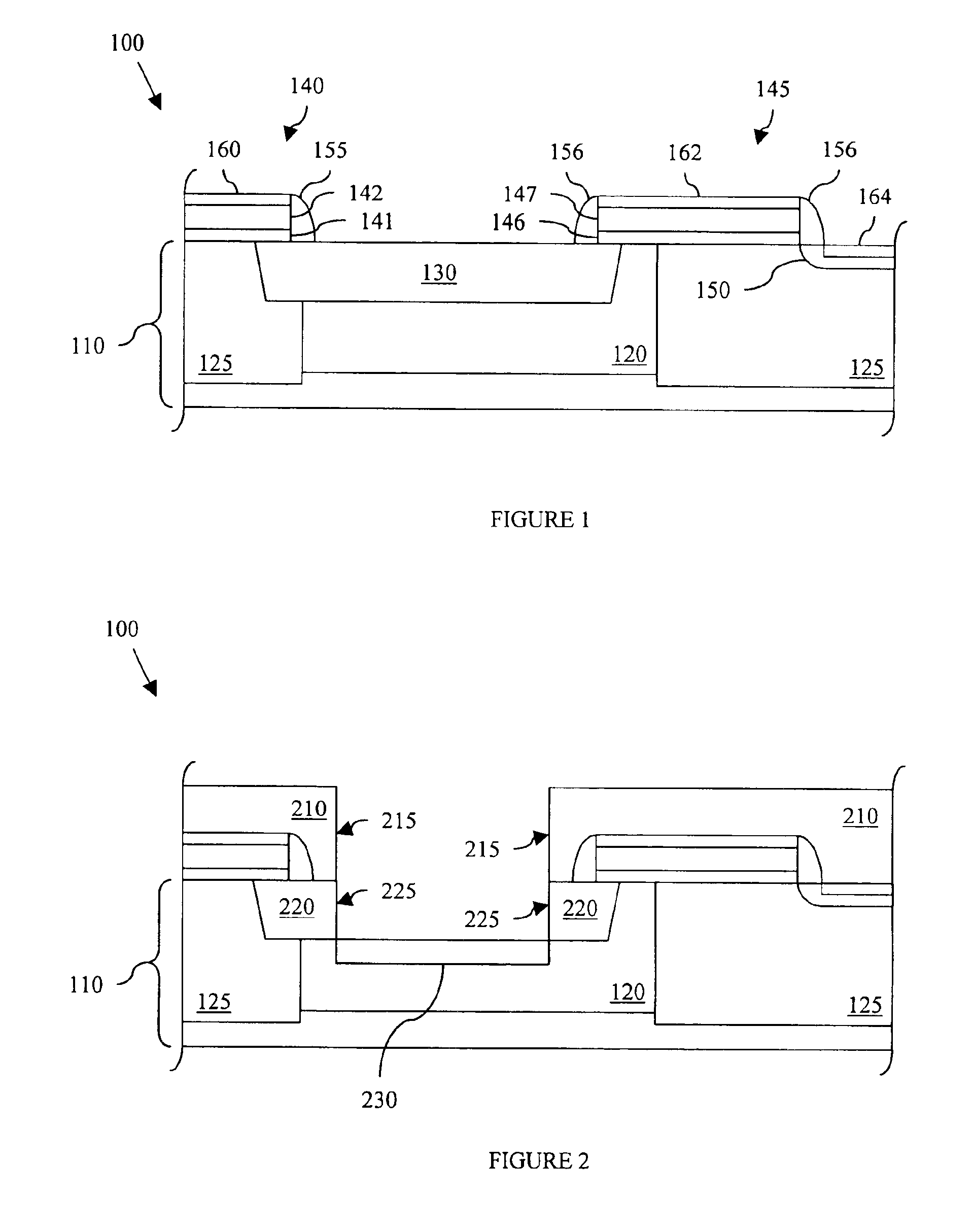
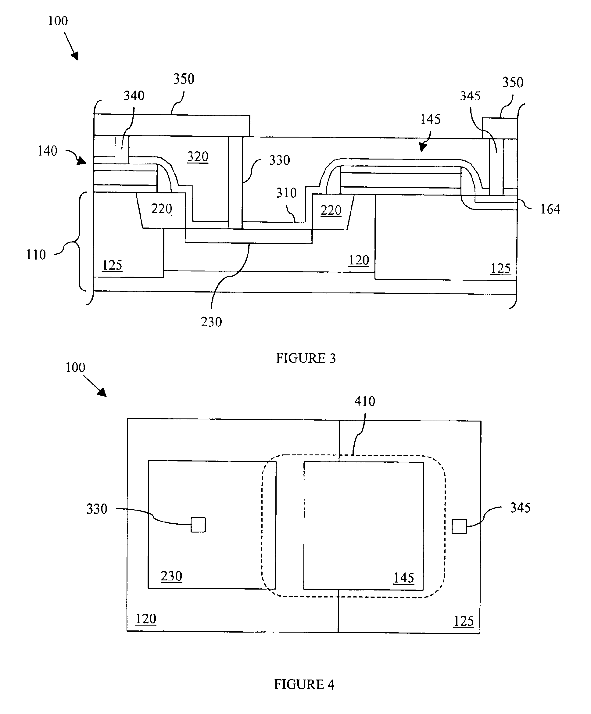
The present invention provides a photodiode with reduced optical interference and a method of manufacturing it. The photodiode includes a well located in a substrate, a floating node located in the well, and shallow trench isolation (STI) regions located over and laterally opposing the floating node. A borderless contact buffer layer is located over at least the floating node, and a dielectric layer is located over the borderless contact buffer layer. A borderless contact extends through the dielectric layer and the borderless contact buffer layer to the floating node. The invention also provides a semiconductor device incorporating a photodiode with reduced optical interference. The technical effects of the invention include reduced optical interference, improved signal-to-noise ratios, and improved device performance.

Problems solved by technology

However, silicides are optically opaque and exhibit excessive junction leakage.
However, the abrupt transition from the relatively low refractive index silicon dioxide layer to the relatively high refractive index silicon layer may cause high reflection of the optical energy.
The borderless contact buffer layer once again introduces optical problems, causing destructive interference attributable to the varying refractive indices of the materials formed over the photodiode.
Such variation in refractive indices through which impinging light must propagate for effective operation of the photodiode will cause destructive interference of the optical signal, especially for signals having wavelengths approaching the thickness of the STI element.

Method used


Image

  • CMOS image sensor device and method
  • CMOS image sensor device and method
  • CMOS image sensor device and method

Examples


Embodiment Construction

[0017]It is to be understood that the following disclosure provides many different embodiments, or examples, for implementing different features of the invention. Specific examples of components and arrangements are described below to simplify the present disclosure. These are, of course, merely examples and are not intended to be limiting. In addition, the present disclosure may repeat reference numerals and / or letters in the various examples. This repetition is for the purpose of simplicity and clarity and does not in itself necessarily dictate a relationship between the various embodiments and / or configurations discussed. Moreover, the formation of a first feature over or on a second feature in the description that follows may include embodiments in which the first and second features are formed in direct physical contact, and may also include embodiments in which additional features may be formed interposing the first and second features, such that the first and second features ...


PUM


Abstract

A photodiode device including a well located in a substrate, a floating node located in the well and shallow trench isolation (STI) regions located over and laterally opposing the floating node. A borderless contact buffer layer is located over at least the floating node, and an interlevel dielectric layer is located over the borderless contact buffer layer. A borderless contact extends through the interlevel dielectric layer and the borderless contact buffer layer to the floating node.

Description

TECHNICAL FIELD[0001]The present invention is directed, in general, to photodiode devices and methods, and, in particular, to CMOS image sensor devices and methods.BACKGROUND[0002]An image sensor is an apparatus for receiving light, i.e., photons, generated by or reflected from an object, and for generating digital image data. The manufacture of one particular type of image sensor may incorporate conventional complementary metal-oxide-semiconductor (CMOS) fabrication technology. Accordingly, such an image sensor is often referred to as a CMOS image sensor (CIS).[0003]Generally, a CMOS image sensor includes a light sensing region for converting photon energy received from an object to an electrical signal (such as current) and a peripheral circuit region for processing and sending the electrical signal to another device for further processing. A photodiode is formed in the light sensing region, and transistors or other devices may be formed in the peripheral circuit region, thereby f...

Claims


Application Information

Patent Timeline
Patent Type & Authority Patents(United States)
IPC IPC(8): G01J1/02H01L21/336H01L21/02H01L21/70H01L21/00H01L27/146H01L21/76H01L31/18H01L21/8238H01L31/10H01L31/0232H01L27/14H01L31/12
CPCH01L27/14603H01L27/1463H01L27/14643H01L27/14689
Inventor YAUNG, DUN-NIAN
Owner TAIWAN SEMICON MFG CO LTD
Learn More