
Multicolor staring missile sensor system

Inactive Publication Date: 2005-09-20
RAYTHEON CO
View PDF20 Cites 50 Cited by
  • Summary
  • Abstract
  • Description
  • Claims
  • Application Information

AI Technical Summary

Benefits of technology

[0005]The present invention provides a sensor system for sensing the energy of a scene, particularly in the infrared range. The sensor system employs a staring sensor, so that there are no moving parts that might reduce its reliability. It may be made in a single-color or multicolor functionality. The sensor system achieves excellent resolution while maximizing sensitivity through a short image integration time that also reduces smearing of the image. The detector is a single-color detector structure, whether the sensor has a single-color or multicolor functionality, so that the development, complexity, and cost associated with a two-color detector are not encountered. The sensor system is packaged in a lightweight, small package that is convenient for many applications.
[0009]The present approach thus provides a single-color or multicolor (two or more colors) staring sensor system. It may use a single detector, even for multicolor sensors, which simplifies the problems of image physical registration and time registration. There is good resolution as well as good sensitivity and short integration times.

Problems solved by technology

Of the various types of seekers, infrared light seekers pose some of the greatest problems to aircraft defense.
The technology of such a two-color detector is complex, still under development, and expected to be relatively expensive when finally perfected.
Additionally, it is expected to have limited resolution, sensitivity, and clutter-rejection capability, particularly when mounted on a fast-moving aircraft platform where there is a tendency for digital images to be smeared in some viewing orientations.

Method used


Image

  • Multicolor staring missile sensor system
  • Multicolor staring missile sensor system
  • Multicolor staring missile sensor system

Examples


Embodiment Construction

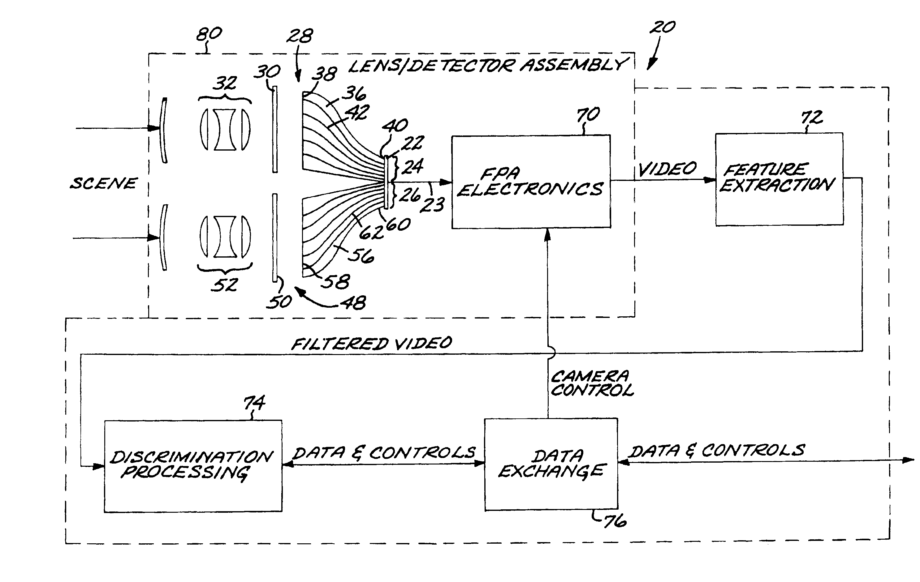
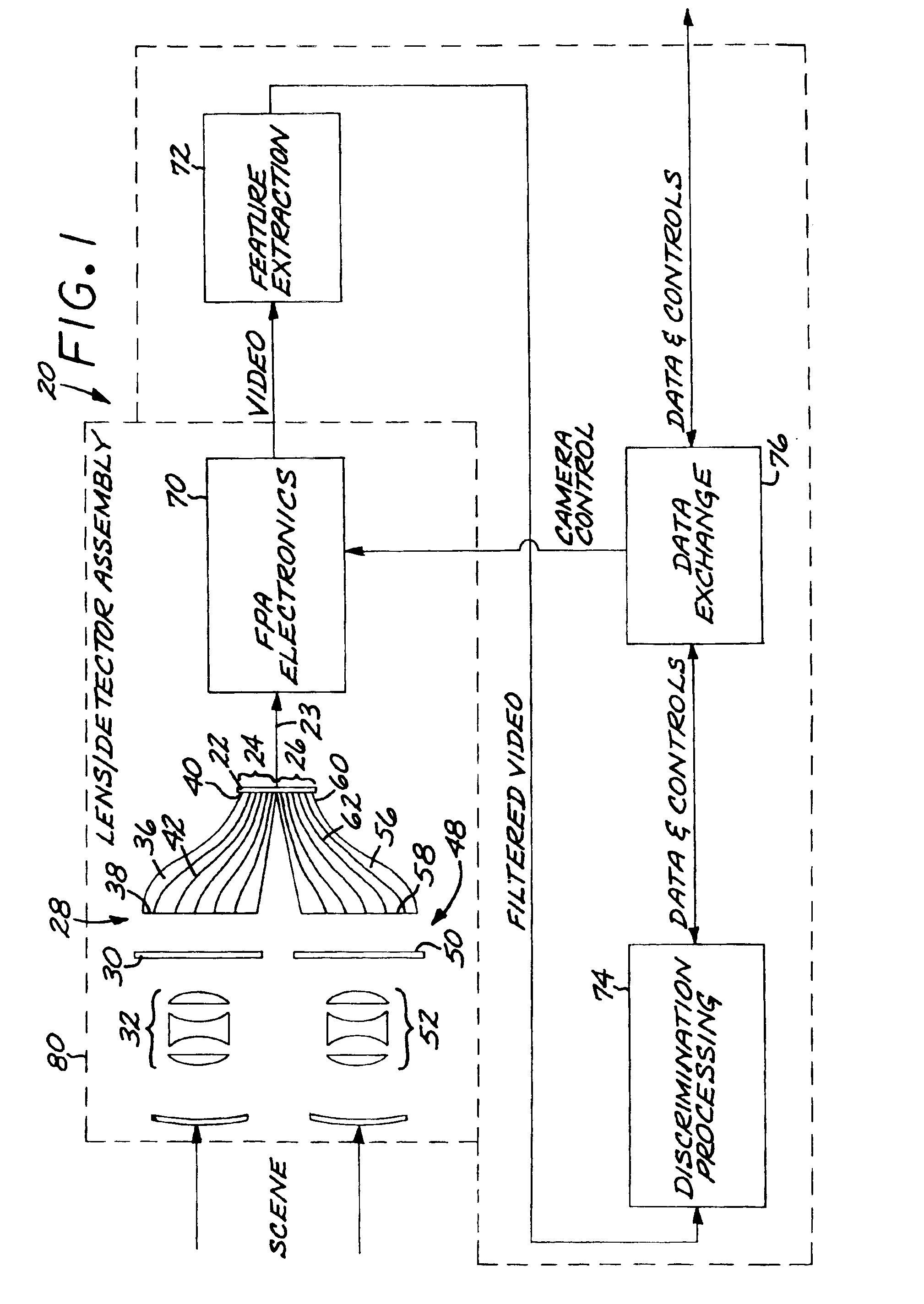
[0015]FIG. 1 depicts a sensor system 20 for viewing light energy from a scene. The sensor system 20 includes a detector 22 which converts incident light energy into an electrical signal 23. The detector 22 preferably comprises an imaging digital focal plane array (FPA) sensitive to a selected wavelength or range of wavelengths of interest. The primary interest of the inventors is light in the infrared, and the detector 22 is sensitive to light in that range. Imaging detectors 22 operable in the infrared are known in the art. In a common case, the imaging detector 22 has a 512×512 detector array of pixels.

[0016]In a preferred embodiment, the detector 22 has a first-color region 24 and a second-color region 26. As will be explained in more detail, this preferred embodiment is a two-color sensor system 20. The desirability of using two colors in sensor systems is known in the art, but the present approach provides an advantageous way for implementing the two-color approach. The present...


PUM


Abstract

A sensor system for viewing the light energy of a scene has an imaging detector which converts incident light energy into an electrical signal. Two colors are separately imaged by the detector in two imaging regions. The imaging system for each color includes a color filter positioned between the scene and the respective region of the detector, an optical train that focuses filtered color scene energy, and an optical fiber bundle having an input end that receives the respective color scene energy from the optical train and an output end that directs the color scene energy onto the respective region of the detector using a nonlinear mapping. The optical fiber bundle is formed of a plurality of optical fibers wherein each of the optical fibers has an input shape and size at its input end and an output shape and size at its output end. The output shape and size are different from the input shape and size. The sensor system further includes an electronic device operable to read the electrical signal of the detector, and image-processing electronics.

Description

[0001]This invention relates to a sensor system, and, more particularly, to a sensor system used to detect threats posed by missiles fired at an aircraft.BACKGROUND OF THE INVENTION[0002]Missiles fired at aircraft are usually guided either by a light seeker or by radar. Of the various types of seekers, infrared light seekers pose some of the greatest problems to aircraft defense. Unlike radar seekers, infrared seekers are passive and do not emit a detectable signal prior to the firing of the missile. Pilots therefore have little warning of their presence prior to the firing of the missile. Infrared-guided missile systems are relatively inexpensive, and human-portable units are widely available.[0003]There has been a continuing effort to develop sensor systems that are carried on aircraft and are used to detect missile threats, particularly infrared-guided missiles. The sensor system must be effective to detect the infrared signature of a relatively small-sized missile at as great a ...

Claims


Application Information

Patent Timeline
IPC IPC(8): G01J3/30G01J3/36G01J3/02G01J3/00G01J1/04G01J1/02G01S3/782H04N5/00
CPCG01J3/02G01J3/0218G01J3/36G02B6/06
Inventor O'NEILL, MARY DOMINIQUEWELLMAN, WILLIAM HALE
Owner RAYTHEON CO
Learn More