

Environmental control system for an aircraft
- Summary
- Abstract
- Description
- Claims
- Application Information
AI Technical Summary
Benefits of technology
Problems solved by technology
Method used
Image

Examples
Embodiment Construction
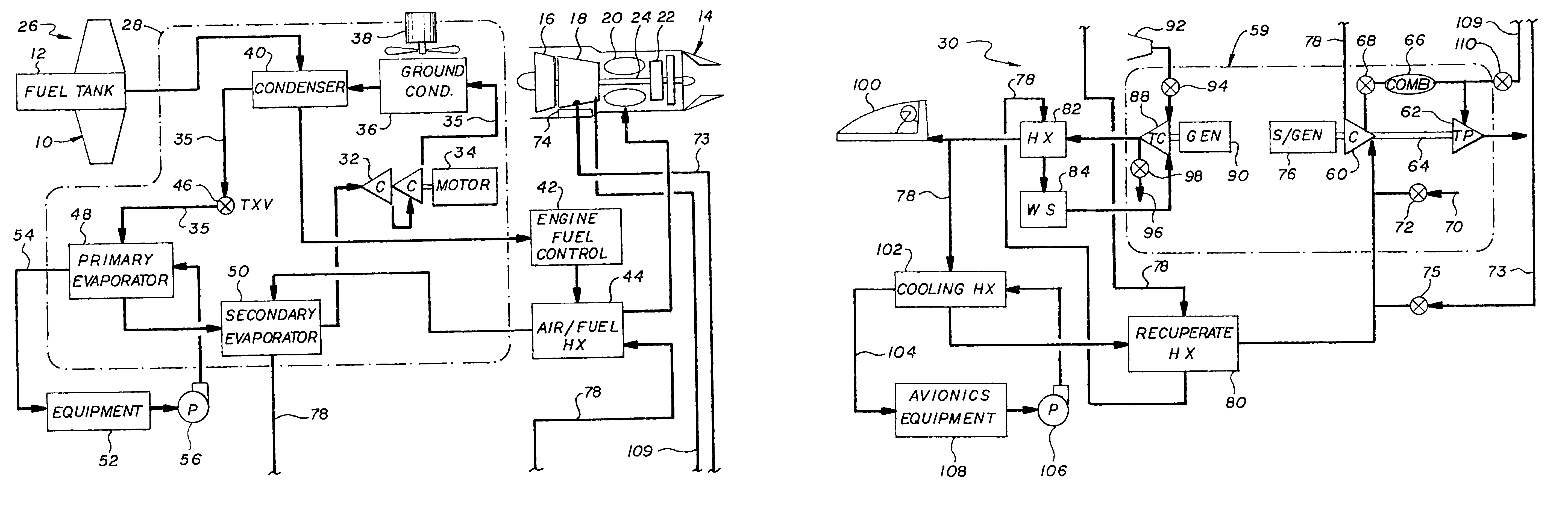
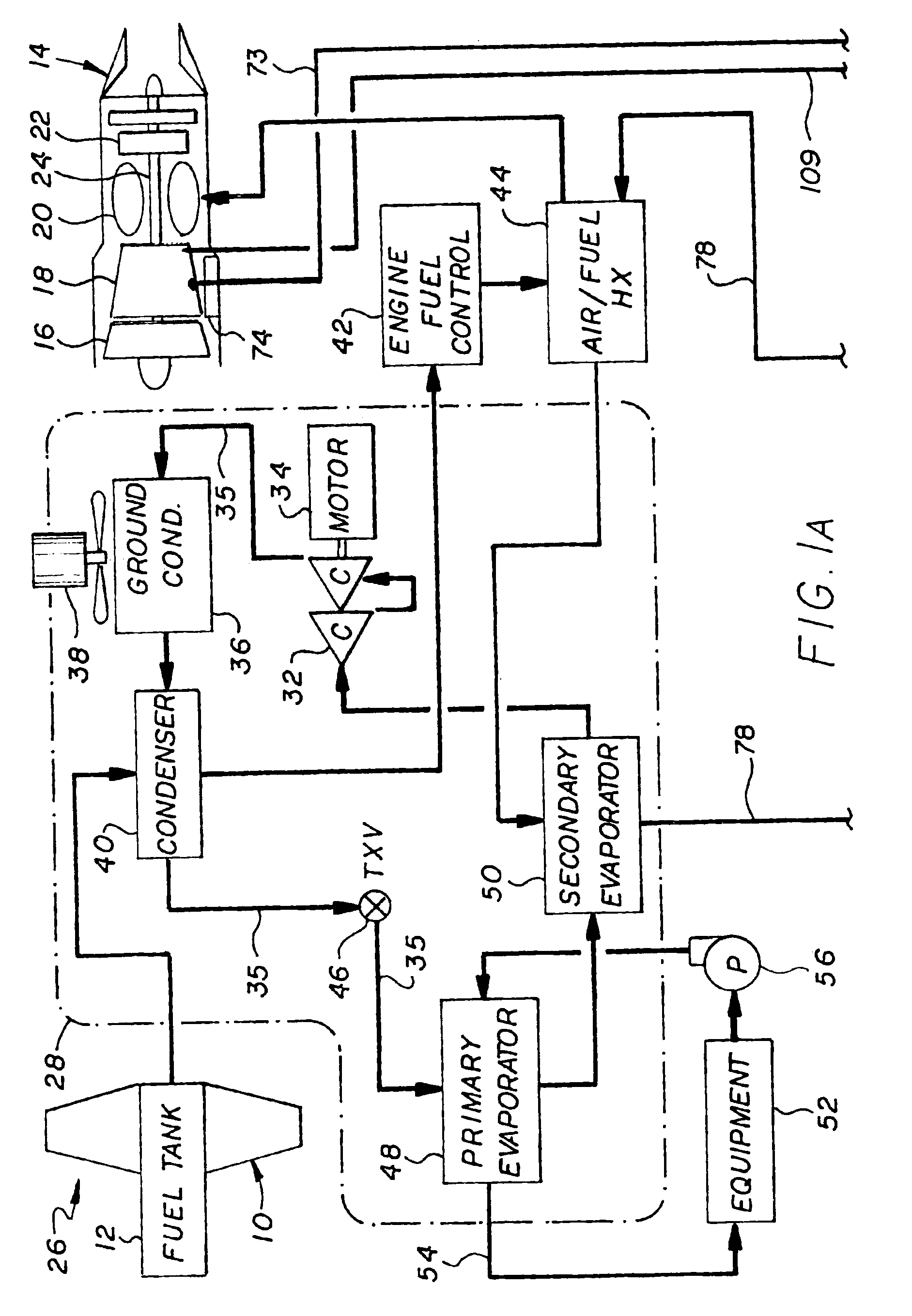
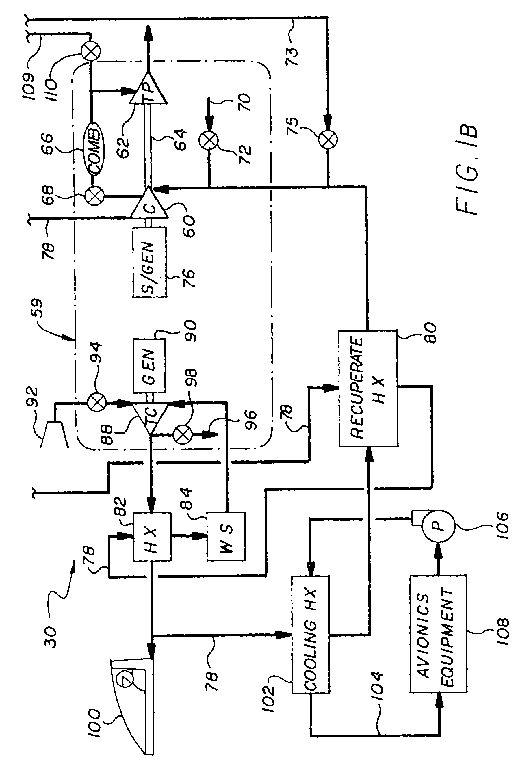
[0017]Referring to FIG. 1 an aircraft 10, including a fuel tank 12 and a jet engine 14. The jet engine 14 includes a fan 16, compressor section 18, combustion section 20 and turbine section 22 for driving the fan and compressor section through a drive shaft assembly 24. The environmental control system, generally indicated by numeral 26 includes a vapor cycle system 28 and an air cycle system 30 that are coupled together.
[0018]The vapor cycle system 28 includes a compressor assembly 32 driven by electric motor 34. The compressor assembly 32 compresses a refrigerant (not shown) where the temperature pressure their of is raised. The refrigerant then passes into a flow path 35 to a ground-cooling condenser 36, for use when the aircraft's engine 14 is off and no fuel is flowing. The refrigerant is cooled by a fan 38. The ground-cooling condenser 36 is coupled to a condenser 40 wherein the refrigerant is cooled while still at high pressure. When the engine 14 is running, cooling is provi...
PUM
 Abstract
Description
Claims
Application Information