

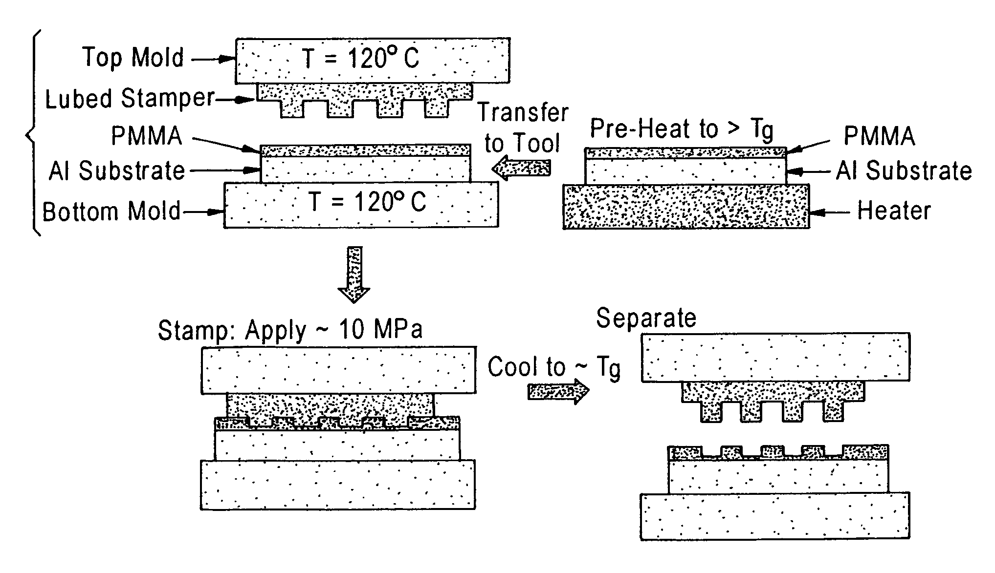
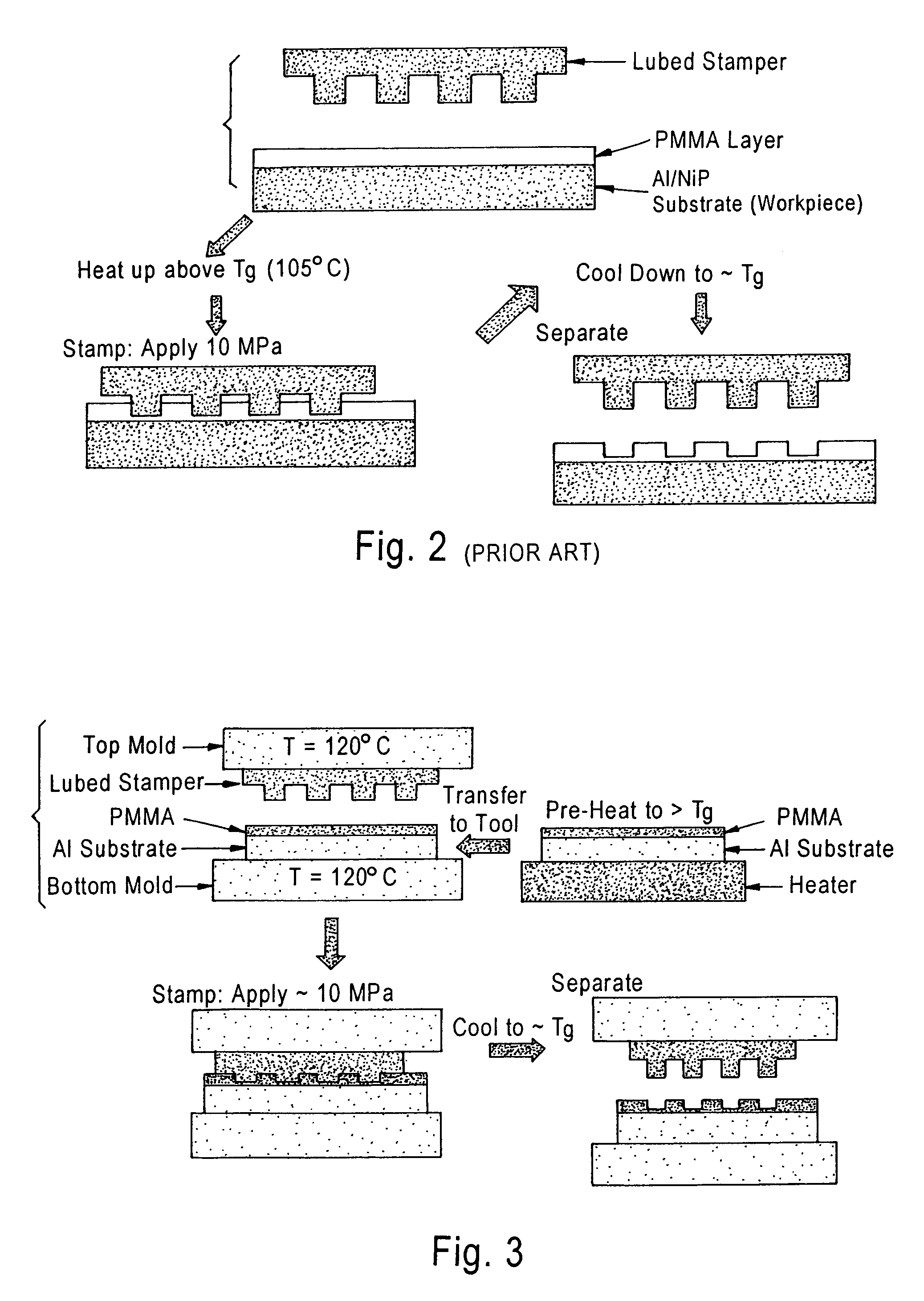
Heat-transfer-stamp process for thermal imprint lithography
a technology of thermal imprint lithography and transfer transfer, which is applied in the direction of maintaining head carrier alignment, photomechanical equipment, instruments, etc., can solve the problems of requiring tax or even exceeding the limits of conventional optical lithographic patterning process utilizing visible light, affecting the efficiency of stamping/imprinting tools, and long thermal cycle intervals, etc., to achieve the effect of eliminating the disadvantageous long interval of thermal cycling of stamping/imprinting tools
- Summary
- Abstract
- Description
- Claims
- Application Information
AI Technical Summary
Benefits of technology
Problems solved by technology
Method used
Image

Examples
Embodiment Construction
[0057]The present invention addresses and solves problems attendant upon the use of thermal imprint lithography, e.g., nano-imprint lithography for forming submicron-dimensioned patterns in a workpiece surface, as in servo patterning of disk-shaped substrates utilized in the manufacture of hard disk recording media. Specifically, the present invention provides a substantial and significant improvement in product throughput, energy consumption, and cost-effectiveness of thermal imprint lithography when performed as part of a continuous, automated manufacturing process, e.g., hard disk manufacture, and is based upon the discovery that the long thermal cycling intervals associated with conventional thermal imprint techniques can be eliminated, or at least substantially reduced, while maintaining full compatibility with all other aspects of conventional automated manufacturing technology for pattern formation by thermal imprint lithography for disk media fabrication.
[0058]According to a...
PUM
| Property | Measurement | Unit |
|---|---|---|
| Temperature | aaaaa | aaaaa |
| Temperature | aaaaa | aaaaa |
| Temperature | aaaaa | aaaaa |
Abstract
Description
Claims
Application Information