
Method and apparatus for treating a waste gas containing fluorine-containing compounds

a technology of fluorine-containing compounds and waste gas, which is applied in the direction of machine/engine, physical/chemical process catalysts, separation processes, etc., can solve the problems of unsatisfactory catalytic compounds, no method has been established to realize a thorough and effective treatment of these harmful gases, and the effect of high decomposition of pfcs

Inactive Publication Date: 2005-09-27
EBARA CORP
View PDF9 Cites 12 Cited by
  • Summary
  • Abstract
  • Description
  • Claims
  • Application Information

AI Technical Summary

Benefits of technology

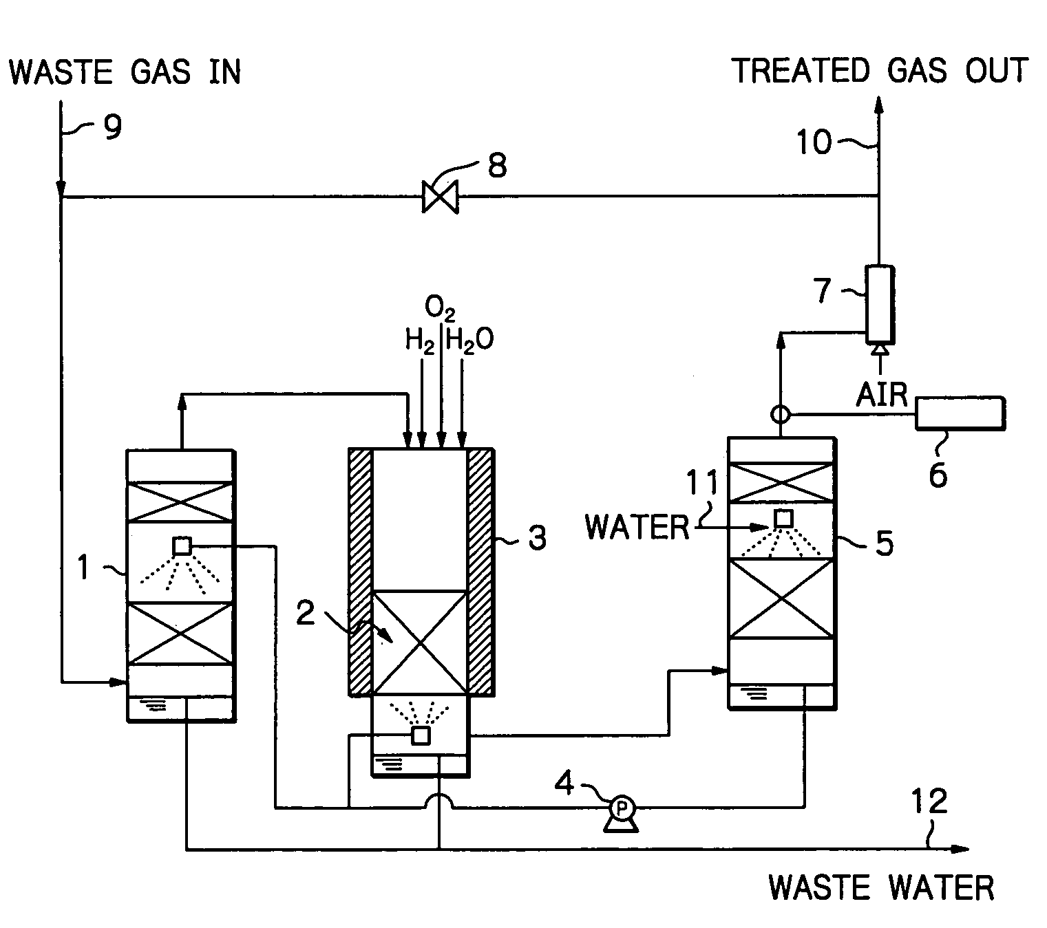
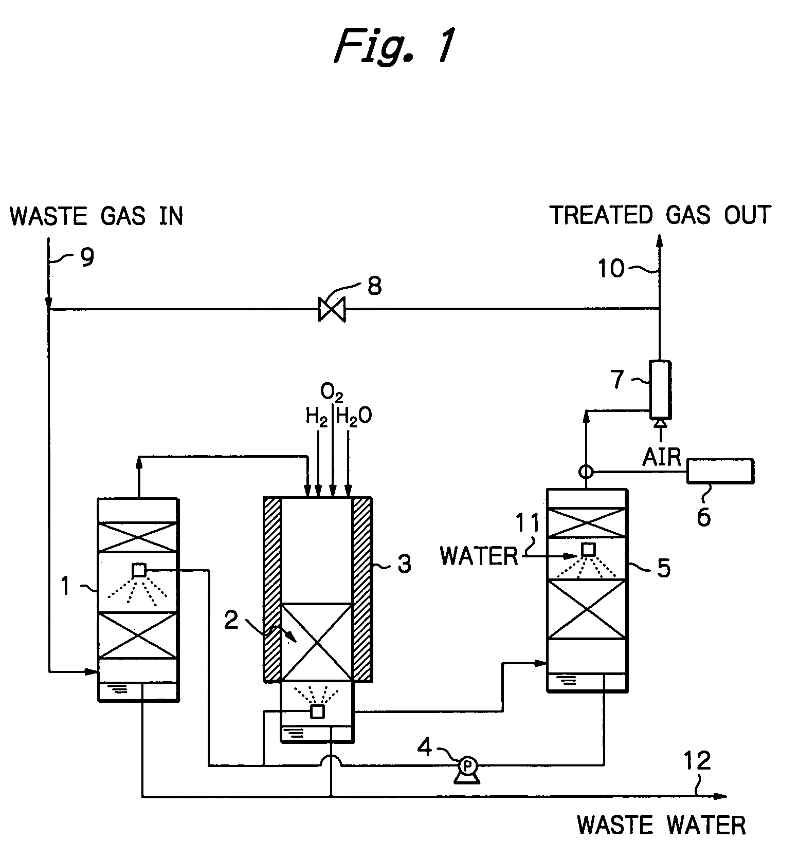
[0007]The present invention has been accomplished under these circumstances and has as an object providing a method for treating waste gases containing fluorine-containing compounds, which method achieves high percent decomposition of PFCs. The method proves to be effective for a prolonged time and simultaneously realizes effective removal of oxidizing gases, acidic gases and CO that are contained in the waste gases.

Problems solved by technology

Semiconductor fabrication plants use many kinds of harmful gases that can potentially pollute the environment.
PFCs contained in waste gases that typically result from etching and CVD steps are suspected of causing global warming, and it is urgently needed to establish an effective system for their removal.
However, none of these catalytic compounds have proved completely satisfactory.
Waste gases discharged from a semiconductor fabrication process contain not only PFCs, but also oxidizing gases such as F2, Cl2 and Br2, acidic gases such as HF, HCl, HBr, SiF4, SiCl4, SiBr4 and COF2, as well as CO; however, no method has yet been established that can realize a thorough and effective treatment of these harmful gases.
If one wants to treat oxidizing gases such as F2, Cl2 and Br2 by a wet method, thorough treatment cannot be achieved by use of water alone.
If alkali agents or reducing agents are also used, not only process control but also a treatment apparatus becomes complicated and, in addition, cost of treatment increases.
However, the lifetime of alumina is very short and throughput or an amount of C2F6 that can be treated for 100% decomposition is only 4.8 L / L.
Additionally, no effective way has been proposed to deal with CO that occurs as a by-product of C2F6 decomposition, and oxidizing gases and acidic gases that occur concomitantly with PFCs.

Method used


Image

  • Method and apparatus for treating a waste gas containing fluorine-containing compounds
  • Method and apparatus for treating a waste gas containing fluorine-containing compounds

Examples


example 1

[0028]An experiment was conducted using a quartz column of 25 mmφ, which was packed with γ-alumina to a height of 100 mm. The γ-alumina was a commercial product of Mizusawa Kagaku K.K. (NEOBEAD GB-08) having a particle size of 0.8 mm. The quartz column was installed in a ceramic electric furnace and the γ-alumina was heated at 800° C.

[0029]In addition to CF4 diluted with N2 gas, H2 and O2 were supplied as decomposition assist gases, with the amount of H2 being such that the number of H atoms was at least equal to the number of F atoms in CF4, and the amount of O2 being at least equimolar to the amount of H2 supplied. These gases were flowed into the column at a total rate of 408 sccm and their entrance concentrations were 1.0% (CF4), 3.0% (H2) and 5.7% (O2).

[0030]In order to evaluate performance of the treatment system, exit gas was analyzed periodically and passage of the CF4, gas was stopped when removal of CF4 dropped below 98%. Throughput was determined from the amount of CF4 th...

example 2

[0034]An experiment was conducted using the same equipment as in Example 1, which was packed with the same γ-alumina in the same amount and heated to the same temperature as that of Example 1. Total gas flow rate was 408 sccm; feed gas was a mixture of N2-diluted CF4 and F2; in addition, H2 and O2 were supplied as decomposition assist gases, with the amount of H2 being such that the number of H atoms was at least equal to the total number of F atoms in CF4 and F2, and the amount of O2 being at least equimolar to the amount of H2 supplied. These gases were flowed into the column at respective concentrations of 0.92% (CF4), 1.1% (F2), 5.0% (H2) and 6.0% (O2).

[0035]As it turned out, the removal of CF4 dropped below 98% when passage of the CF4 / F2 gas continued for 25 hours. At this point in time, throughput was 115 L / L, which was 1.51 times higher than the throughput for the case where only CF4 gas was supplied. Throughout the experiment, concentrations of CO and F2 were below tolerable...

reference example 1

[0036]An experiment was conducted using the same equipment as in Example 1, which was packed with the same γ-alumina in the same amount and heated to the same temperature as that of Example 1. The total gas flow rate was 408 sccm; in addition to N2-diluted CO, O2 was supplied in moles at least equal to the moles necessary for CO to be converted into CO2, and their respective entrance concentrations were 1.4% (CO) and 5.7% (O2). Throughout passage of a feed gas for 30 minutes, concentration of CO was below the detection limit (2 ppm), and all of CO had been oxidized into CO2.


PUM

PropertyMeasurementUnit
particle sizeaaaaaaaaaa
heightaaaaaaaaaa

Abstract

An apparatus for treatment of a waste gas, containing fluorine-containing compounds, comprises: a solids treating device for separating solids from the waste gas; an addition device for adding H2 and / or H2O, or H2 and / or H2O and O2, as a decomposition assist gas to the waste gas leaving the solids treating device; a thermal decomposition device that is packed with γ-alumina heated at 600–900° C., and which thermally decomposes the waste gas to which the decomposition assist gas has been added; an acidic gas treating device for removing acidic gases from the thermally decomposed waste gas; and channels or lines for connecting these devices in sequence. The apparatus preferably includes an air ejector which is capable of adjusting an internal pressure of the apparatus.

Description

BACKGROUND OF THE INVENTION[0001]This invention relates to treatment of a waste gas containing fluorine-containing compounds. More particularly, it relates to a method and an apparatus for efficient treatment of emissions from semiconductor fabrication plants, particularly from steps of dry cleaning an inner surface of a fabrication apparatus and etching various kinds of deposited films with perfluorocarbons (PFCs) and halogenated hydrocarbons such as C2F6, C3F8, CHF3, SF6 and NF3. The waste gases contain not only PFCs but also oxidizing gases such as F2, Cl2 and Br2, acidic gases such as HF, HCl, HBr, SiF4, SiCl4, SiBr4 and COF2, as well as CO.[0002]Semiconductor fabrication plants use many kinds of harmful gases that can potentially pollute the environment. PFCs contained in waste gases that typically result from etching and CVD steps are suspected of causing global warming, and it is urgently needed to establish an effective system for their removal.[0003]Various breaking and rec...

Claims


Application Information

Patent Timeline
Patent Type & Authority Patents(United States)
IPC IPC(8): B01D53/86B01D53/68B01D53/70B01D53/34B01J21/04
CPCB01D53/685B01D53/70B01D53/8659B01D53/8662B01D2257/204B01D2257/2066Y02C20/30
Inventor MORI, YOICHIKYOTANI, TAKASHISHINOHARA, TOYOJI
Owner EBARA CORP
Learn More