Method and system for controlling temperature of an internal combustion engine exhaust gas aftertreatment device

US6951098B2Active Publication Date: 2005-10-04FORD GLOBAL TECH LLC

Image

  • Method and system for controlling temperature of an internal combustion engine exhaust gas aftertreatment device
  • Method and system for controlling temperature of an internal combustion engine exhaust gas aftertreatment device
  • Method and system for controlling temperature of an internal combustion engine exhaust gas aftertreatment device

Examples


Embodiment Construction

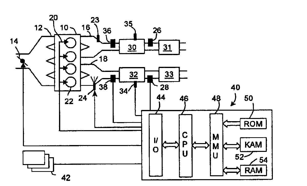
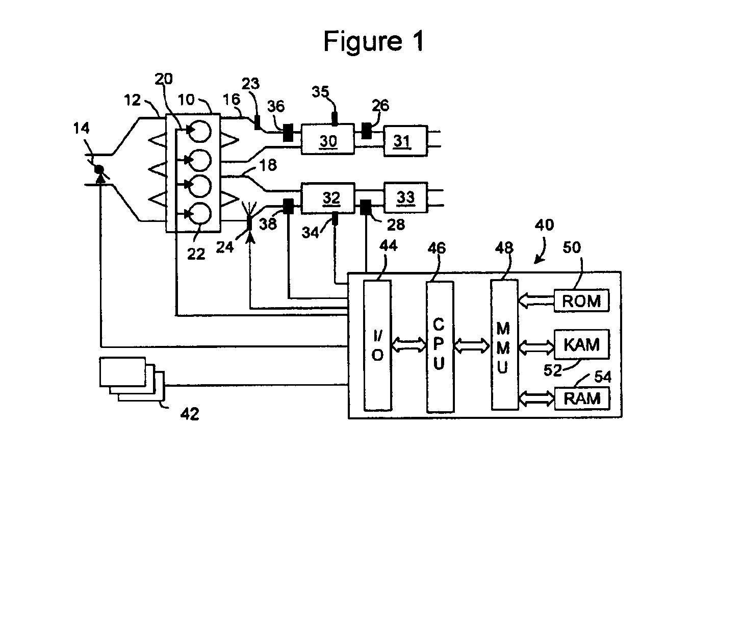
[0020]In FIG. 1, an internal combustion engine 10 is shown. Engine 10 is, preferably, a diesel engine. However, the invention claimed herein is applicable to other engines such as spark-ignited gasoline engines or homogeneous charge compression ignition engines.

[0021]FIG. 1 shows, by way of example, a 4-cylinder engine 10. Engines having 6, 8, 10, 12 or other even number of cylinders can be used for this invention, having the exhaust collected into at least 2 paths. Engine 10 is supplied air through an intake manifold 12 with a throttle valve 14. Typically, diesel engines are equipped with a throttle valve 14 or exhaust pressure control to cause a pressure depression between exhaust manifold 16 and intake manifold 12, even during boosted operation, so exhaust gases can be recirculated from the exhaust system through an exhaust gas recirculation system (not shown). Fuel injectors 20 supply fuel into cylinders 22 of engine 10. Engine 10 has two cylinders supplying exhaust gases to exh...


PUM


Abstract

A method for controlling torque in an internal combustion engine to cause an increase in temperature in an exhaust aftertreatment device is disclosed. One group cylinders feed exhaust gases to one exhaust aftertreatment device and another group of cylinders feed exhaust gases to another exhaust aftertreatment device. By operating the groups of cylinders at different operating conditions, the desired temperature in one of the exhaust aftertreatment devices can be achieved while also providing driver demanded torque.

Description

BACKGROUND OF INVENTION[0001]1. Field of the Invention[0002]The present invention relates to internal combustion engines and more particularly to methods and systems for controlling temperature of exhaust gas aftertreatment devices used with such engines.[0003]2. Background of the Invention[0004]As is known in the art, exhaust gas aftertreatment devices are generally used with vehicular internal combustion engines. One type of such device is a particulate filter type device. Such (PF) device traps carbon particles from the exhaust gas stream of the engine. Over time, PF becomes occluded with carbon particles. If allowed to continue, flow through PF can become impeded. To avoid deleterious effects on the engine, the PF is regenerated by the reaction of soot with NO2 or O2. In the former PF regeneration method, an oxidation catalyst is placed upstream of the PF or the PF is coated with precious metal, thereby oxidizing NO in the exhaust gas to NO2 for regeneration of the PF. To effici...

Claims


Application Information

Patent Timeline
04 Oct 2005
Publication
US6951098B2
IPC
F01N3/20; F01N3/023; F01N3/08; F02D41/14; F01N11/00; F02D41/02; F02D41/34; F01N7/00; F01N7/02; F01N9/00; F02B1/12; F02B37/00; F02B1/00; F01N13/02; F02D41/00
CPC
F01N3/023; F01N3/0885; F01N3/206; F01N9/005; F01N11/007; F02D41/0082; F02D41/024; F02D41/027
Inventors
XU, LIFENG; YANG, JIALIN