Wind turbine ring/shroud drive system

a drive system and wind turbine technology, applied in the direction of marine propulsion, vessel construction, other chemical processes, etc., can solve the problems of hardware costs the hardware cost of the turbine is directly affecting the initial capital cost, and the upwind rotor design currently in use is not operated at optimum structural efficiency

Inactive Publication Date: 2005-10-04
GENERAL ELECTRIC CO
View PDF5 Cites 166 Cited by
  • Summary
  • Abstract
  • Description
  • Claims
  • Application Information

AI Technical Summary

Benefits of technology

[0020]It is also an object and feature of the subject invention to provide a standardized ring/shroud and hub geometry for a given family of turb

Problems solved by technology

Upwind rotor designs currently in use are not operated at optimum structural efficiency.
These are the cost of turbine hardware and the turbine

Method used


Image

  • Wind turbine ring/shroud drive system
  • Wind turbine ring/shroud drive system
  • Wind turbine ring/shroud drive system

Examples


Embodiment Construction

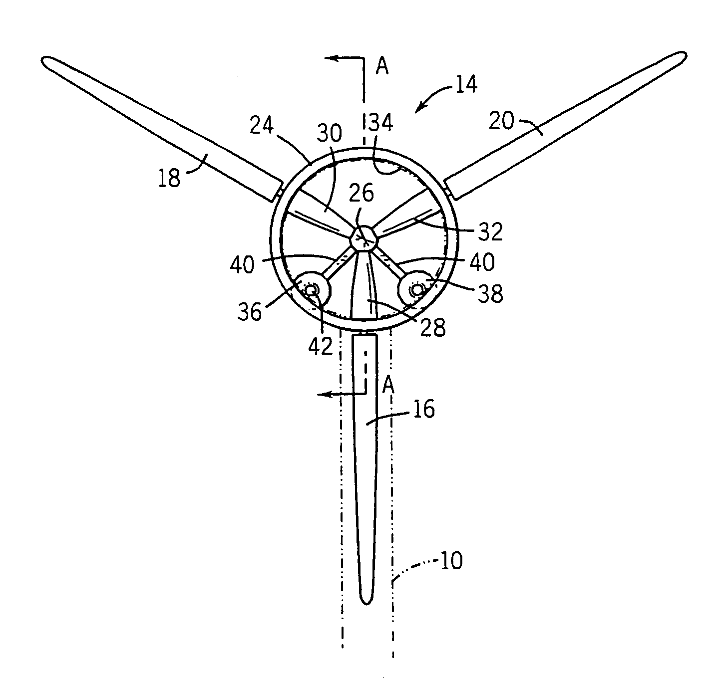
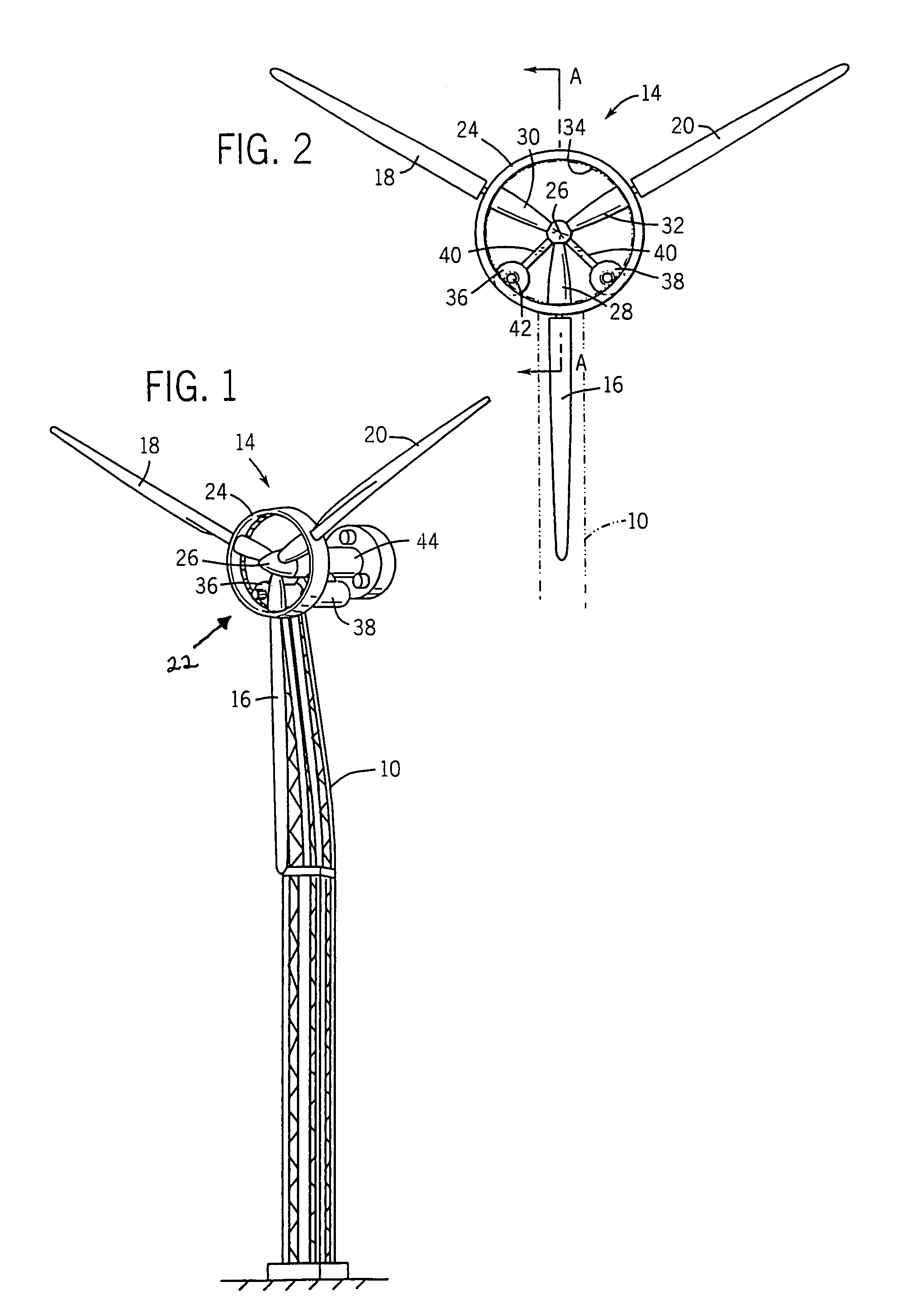
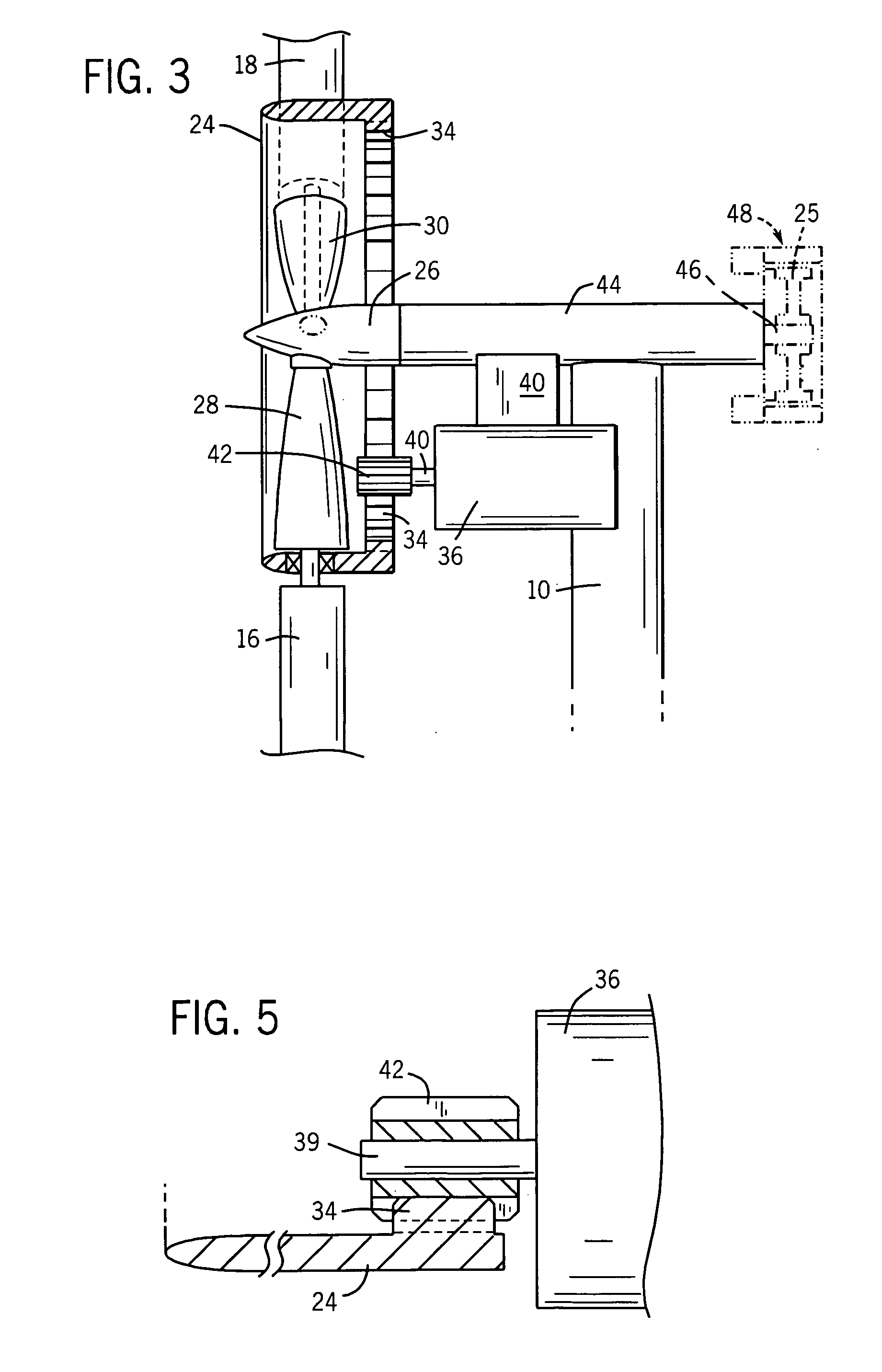
[0027]The overall system design is shown in FIG. 1. FIG. 1 illustrates the tower 10 and the housing 44. The subject invention is specifically directed to the ring / shroud 14 and the connection assembly thereof for the blades 16, 18 and 20 and the generator assembly 22. An enlarged front view of the ring / shroud 14 is shown in FIG. 2. The outer ring 24 is concentric with a hub 26 and is connected thereto via permanently mounted interior blades or other interconnecting structure 28, 30 and 32 (also see FIG. 3). The interior blades may be either fixed or variable pitch. In the preferred embodiment, the shroud includes a gear track or race 34 about its perimeter, see FIG. 3. The track can be on the inner perimeter as shown in FIGS. 3 and 5, or can be along the outer perimeter, as a matter of choice. In the preferred embodiment, one or more generators 36, 38 are mounted on struts 40 that extend radially outward from the nacelle 44. As is better shown in the enlarged fragmentary view FIG. 5...


PUM


Abstract

A wind turbine capable of driving multiple electric generators having a ring or shroud structure for reducing blade root bending moments, hub loads, blade fastener loads and pitch bearing loads. The shroud may further incorporate a ring gear for driving an electric generator. In one embodiment, the electric generator may be cantilevered from the nacelle such that the gear on the generator drive shaft is contacted by the ring gear of the shroud. The shroud also provides protection for the gearing and aids in preventing gear lubricant contamination.

Description

GOVERNMENT INTEREST[0001]This Invention was made with Government support under NREL Subcontract No. ZAM-7-13320-26, Prime Contact DE-AC36-83CH10093 awarded by the Department of Energy. The Government has certain rights in this Invention.BACKGROUND OF THE INVENTION[0002]1. Field of the Invention[0003]The subject invention is related to wind turbines and is specifically directed to shroud and ring gear drive configurations for reducing gear tooth loading and thereby increasing gearbox torque transmission capability by reducing gear tooth tangential force.[0004]2. Description of the Prior Art[0005]Wind turbines, like other energy conversion devices, require fuel. It is the quantity of fuel available to the device and the overall conversion efficiency that ultimately determine the net power output. In the case of a wind turbine, air is the fuel. The quantity of air available to the turbine is determined by the diameter of the rotor and the elevation at which the rotor is positioned. A l...

Claims


Application Information

Patent Timeline
IPC IPC(8): F03D7/02F03D7/00F03D9/00F03D11/02
CPCF03D7/0224F03D9/002F03D11/02F05B2240/40F05B2260/4031Y02E10/722Y02E10/723Y02E10/725Y10S416/04Y10S415/908F03D9/25F03D15/00F03D15/10Y02E10/72
Inventor BLAKEMORE, RALPH W.
Owner GENERAL ELECTRIC CO
Why Eureka
Try Eureka