Correcting device, exposure apparatus, device production method, and device produced by the device production method

a technology of exposure apparatus and correction device, which is applied in the field of exposure apparatus, can solve the problems of material to be processed getting scratched or defective, mask damage, and similar damage to the mask

Inactive Publication Date: 2005-10-04
CANON KK
View PDF11 Cites 9 Cited by
  • Summary
  • Abstract
  • Description
  • Claims
  • Application Information

AI Technical Summary

Benefits of technology

[0012]In general, it is an object of the present invention to provide a novel, useful correcting device, exposure apparatus, device production method, and device produced by the production method, which make it possible to overcome these conventional problems.
[0013]More specifically, it is an object of the present invention to provide, for illustrative purposes, a correcting device that properly maintains the flatness of a mask, and an exposure apparatus and a device production method, which make it possible to increase overlay accuracy by making use of the correcting device.

Problems solved by technology

However, in the former method, although a high resolution can be obtained, the mask gets damaged and the material to be processed gets scratched or defective due to dust or pieces of silicon being pressed into the mask.
In the latter method, the problem that exists in the former method is initially solved, but, when the separation between the mask and the material to be processed becomes smaller than the maximum size of dust particles, damage to the mask similarly occurs.
However, when the optical axis substantially coincides with the direction of gravitational force, the center portion of the mask is flexed by an amount on the order of a few microns in the direction of the gravitational force due to its own weight, resulting in a problem that overlay accuracy is reduced during the exposure.
More specifically, the following problems arise: (1) Distortion of a projected image of the pattern changes as a result of distortion of the mask pattern, and (2) focal depth, which is the focal range that allows a certain image-formation performance to be maintained, is reduced by curvature of field.
However, when the mask is enclosed, heat produced by exposure causes the mask to be distorted, so that this method is not a preferable method.
However, the use of the piezoelectric device around the mask is not necessarily effective in removing flexure of the center portion of the mask caused by its own weight.
However, it is difficult to uniformly apply pressure to the mask.
In addition, it is difficult to dispose gas blowing means while maintaining an exposure optical system.

Method used


Image

  • Correcting device, exposure apparatus, device production method, and device produced by the device production method
  • Correcting device, exposure apparatus, device production method, and device produced by the device production method
  • Correcting device, exposure apparatus, device production method, and device produced by the device production method

Examples


Embodiment Construction

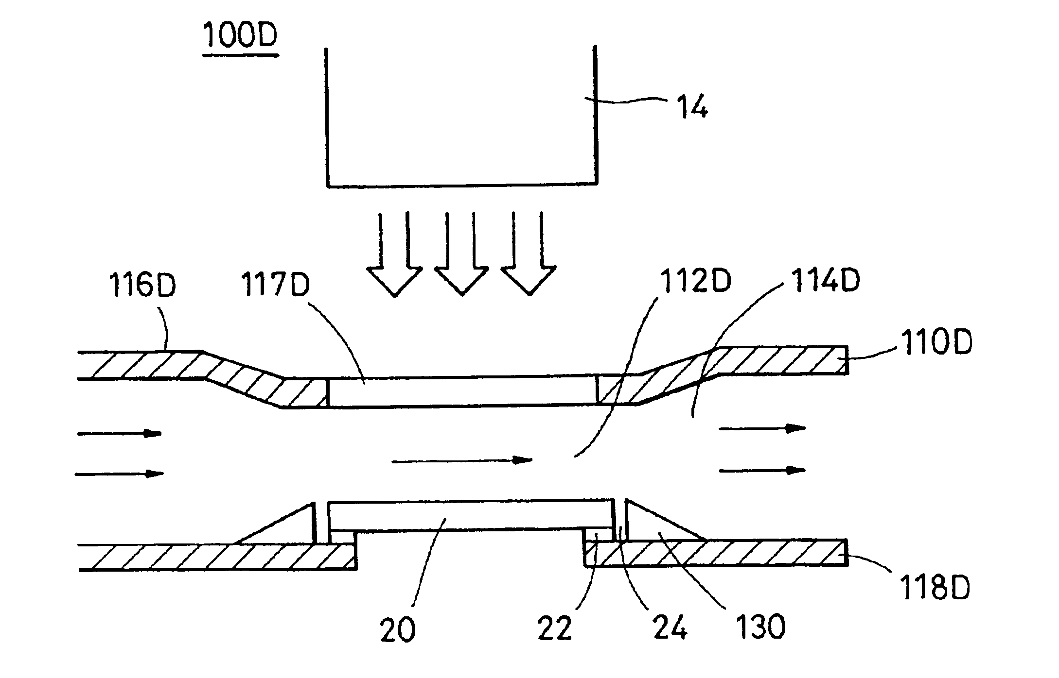
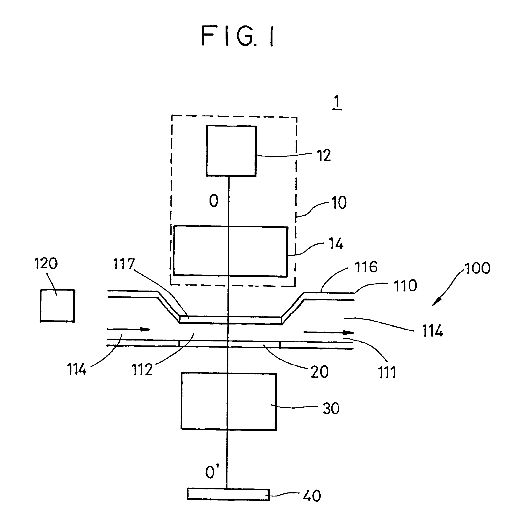
[0044]Hereafter, for illustrative purposes, an exposure apparatus 1 of the present invention will be described with reference to the attached drawings. FIG. 1 shows an optical path of a simplified optical system of the illustrative exposure apparatus 1 of the present invention.

[0045]As shown in FIG. 1, the exposure apparatus 1 comprises an illumination device 10, a reticle 20, a projection optical system 30, a plate 40, and a correcting device 100. The exposure apparatus 1 is a scanning projection exposure apparatus which, by exposure, projects a circuit pattern formed on the reticle 20 onto the plate 40 by the step-and-repeat projection exposure method or the step-and-scan projection exposure method.

[0046]The illumination device 10 illuminates the reticle 20 on which the circuit pattern to be transferred is formed, and comprises a light source 12 and an illumination optical system 14.

[0047]For the light source 12, a laser may be used. For the laser, an ArF excimer laser having a wa...


PUM

PropertyMeasurementUnit
wavelengthaaaaaaaaaa

Abstract

A correcting device that properly maintains the flatness of a mask, an exposure apparatus in which overlay accuracy is increased by making use of the correcting device, and a device production method. The correcting device includes a gas flow path including a first area and a second area. The first area is formed above a reticle having formed thereon a pattern that is projected onto a material to be processed in order to form an image of the pattern on the material to be processed. The second area is connected to the first area, has a cross-sectional area that is different from that of the first area, and is not disposed in line with the reticle. The correcting device also includes a blowing section that blows gas to the gas flow path.

Description

BACKGROUND OF THE INVENTION[0001]1. Field of the Invention[0002]In general, the present invention relates to an exposure apparatus. More particularly, the present invention relates to an exposure apparatus used to expose a material to be processed, such as a monocrystalline substrate for a semiconductor wafer or a glass substrate for a liquid crystal display (LCD), a correcting device that corrects deformation of a mask or a reticle (hereafter, these terms are used interchangeably in the application) used in the exposure apparatus, a device production method using the material to be processed, and a device that is produced from the material to be processed. The present invention is, for example, suitable for application to an exposure apparatus which exposes a monocrystalline substrate for a semiconductor wafer by the step-and-scan projection method, the scan projection method, or the step-and-repeat projection method in a photolithography process.[0003]Here, the step-and-scan proje...

Claims


Application Information

Patent Timeline
Patent Type & Authority Patents(United States)
IPC IPC(8): G03F7/20H01L21/67H01L21/68H01L21/027
CPCG03F7/70691G03F7/70783H01L21/682G03F7/70875Y10T29/41
Inventor TANAKA, NOBUYOSHISAKAMOTO, EIJI
Owner CANON KK
Why Eureka
Try Eureka